Continue to Site

Welcome to EDAboard.com

Welcome to our site! EDAboard.com is an international Electronics Discussion Forum focused on EDA software, circuits, schematics, books, theory, papers, asic, pld, 8051, DSP, Network, RF, Analog Design, PCB, Service Manuals... and a whole lot more! To participate you need to register. Registration is free. Click here to register now.

How to lower VSWR for dipole antenna using HFSS?

Status
Not open for further replies.

shaikss

Full Member level 4
Joined
Jun 18, 2007
Messages
229
Helped
1
Reputation
2
Reaction score
1
Trophy points
1,298
Activity points
3,319
S and Z-parameters for dipole antenna using HFSS?

Folks,

I am trying to design an antenna for UHF RFID, resonating at 865MHz using HFSS.
I started with a simple dipole antenna.

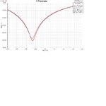
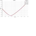
But when I tried to simulate the same using HFSS, I had seen VSWR > 2, in the order of seven.
What are the different methodologies to be used to have antenna with lower VSWR?

I have taken the design parameters as below:
Lambda = 346mm
gap_src = 1.2mm
res_length = 0.48 * lambda
dip_length = res_length - gap_src/2
dip_radius = lambda/200
radiation_rad = dip_radius + lambda/4
radiation_height = dip_length + gap_src/2 +lambda/10


I have attached .hfss file and the results.

I tried to vary the gap_src from 0.125 to 1.5 and multiple of lambda for resonating length from 0.45 to 0.5. I have succeeded in getting VSWR < 2 but S-parameters are high and couldn't succeed in acheiving z-parameters. I am unable to get all correct parameters at a single shot. Pls help me in solving this.

Thanks!
 

Attachments

  • dipole_uhf.rar
    22.7 KB · Views: 116
  • exportparams.txt
    969 bytes · Views: 70
  • s.JPG
    s.JPG
    71.1 KB · Views: 145
  • vswr.JPG
    vswr.JPG
    76.9 KB · Views: 135
Last edited:

I don't have time to look now - just going out. In any case, I'm no HFSS expert. But a dipole can be expected to have an SWR of about 1.47:1, as the impredance of a dipole is about 72/73 Ohms when resonate, so it will never be great into 50 Ohms.

If you want it lower, one method is to fold the dipole, using a different thickness for each half of the element. Then you can make it 200 Ohms with a 4:1 balun.
 

Shaik when you get a vswr<2 it implies your s parameters are less than-10 dB.coz they are both inter related.coming back to Z-parameters. if you are getting a good vswr there is no way you wont have Z-parameters in line with input impedance you are supposed to see.post your file here

Regards
ChachitoEl
 

Shaik.I have checked your file, you have not assigned your integration line properly.the line doesnt go from one point to another.i am gonna post your file,but the file is in Hfss13 format,not sure if you have it.

There was no problem whatsoever in your file except that you didn't assign the integration line properly from where it emanates and where it ends. integration line was hanging in between without touching one of the cylinders.

Regards
ChachitoEL
 

Attachments

  • dipole_uhf.rar
    24.1 KB · Views: 119

Shaik.I have checked your file, you have not assigned your integration line properly.the line doesnt go from one point to another.i am gonna post your file,but the file is in Hfss13 format,not sure if you have it.

There was no problem whatsoever in your file except that you didn't assign the integration line properly from where it emanates and where it ends. integration line was hanging in between without touching one of the cylinders.

Regards
ChachitoEL

What is the general way to draw the integration line? Is it required to touch any of the cylinders or both the cylinders?
Pls clarify.

---------- Post added at 06:58 ---------- Previous post was at 06:28 ----------

Shaik.I have checked your file, you have not assigned your integration line properly.the line doesnt go from one point to another.i am gonna post your file,but the file is in Hfss13 format,not sure if you have it.

There was no problem whatsoever in your file except that you didn't assign the integration line properly from where it emanates and where it ends. integration line was hanging in between without touching one of the cylinders.

Regards
ChachitoEL

What is the general way to draw the integration line? Is it required to touch any of the cylinders or both the cylinders?
Pls clarify.
 

The general way is that the integration line goes from one side to the other,representing the ground and positive. hope that helps

Regards
 

The general way is that the integration line goes from one side to the other,representing the ground and positive. hope that helps

Regards

which means it has to touch the end of two cylinders right.When I tried to draw the integration line, from bottom center of the source to the other end of the source, touching the cylinder, I got a msg that the definition of new line is invalid.

can you explain how you had drawn the integration line? I am sorry for bothering you a lot but your clarification is helping a lot to understand the HFSS concepts.
 

You have to begin from the lower centre or upper centre of the rectangle and then go all the way to the centre of the opposite side.Hope that helps. i'm out if you have any questions post them,will reply later.

Regards
 

You have to begin from the lower centre or upper centre of the rectangle and then go all the way to the centre of the opposite side.Hope that helps. i'm out if you have any questions post them,will reply later.

Regards

Ia m also having same problem...i am simulating dipole antenna to get omni pattern .ona thing is i dont knw how and on what basis parameters should be changed and other is integration line is not being drawn properly..
 
Ia m also having same problem...i am simulating dipole antenna to get omni pattern .ona thing is i dont knw how and on what basis parameters should be changed and other is integration line is not being drawn properly..

Are you talking about a wire dipole?
 

yes i am simulating wired diapole to get omni pattern

Do yourself a favor. Stop using HFSS and start reading basic antenna books. If you don't know a vertically polarized dipole will give you omnidirectional radiation, then you should defiantly not be using HFSS. You obviously don't understand the basics, so there is no point using advanced software like HFSS.

Sorry to be blunt, but I doubt there is a competent RF engineer who would argue with my advice.
 

Status
Not open for further replies.

Part and Inventory Search

Welcome to EDABoard.com

Sponsor

Back
Top