Continue to Site

Welcome to EDAboard.com

Welcome to our site! EDAboard.com is an international Electronics Discussion Forum focused on EDA software, circuits, schematics, books, theory, papers, asic, pld, 8051, DSP, Network, RF, Analog Design, PCB, Service Manuals... and a whole lot more! To participate you need to register. Registration is free. Click here to register now.

How to invert the ZX edge on every half cycle

Status
Not open for further replies.

dattlara76

Junior Member level 2
Joined
Mar 1, 2019
Messages
21
Helped
0
Reputation
0
Reaction score
0
Trophy points
1
Activity points
291
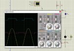
I’m making a dimmer for 230V AC/50Hz bulbs. I use PIC12F675 with 1M ohm(from Neutral of AC230V) ZX detection on external interrupt pin.

When it comes to zero cross most people say that when it detects a ZX you turn on a timer & when timer expires you fire the triac. & invert the ZX edge on every half cycle. So you can catch the negative cycle as well.
For that i want to use timer1 as firing delay and INT Pin for ZC detection. MCU run internal 4MHZ. I want to use Timer0 and IOC for IR decoding.

1) ISR Init as below:
Code:
/////////////////initial ISR///////////////////
void interrupt tintr(void)
{ 
   if(INTCONbits.INTF)               //Check RB0 PIN INTERRUPT FOR ZC FLAG
   {
     //INT pin has detected falling
     TMR1H = 0xF7;
     TMR1L = 0xFF; 
     T1CONbits.TMR1ON=1; //timer1 on
     dimmerdelay[0]=(DIMMER_MAX-dimmerspeed[0])<<1;   //dimmerspeed has already updated in main()
     timer1Isr();

      //INT Edge change for next half cycle
      if (ZERO_CROSS == 0) { OPTION_REGbits.INTEDG = 1;}  
      else       OPTION_REGbits.INTEDG = 0;
        
      INTCONbits.INTF   =0;
   }
     
   else if(PIR1bits.TMR1IF)               // check the timer1 over flow interrupt flag
   {
   timer1Isr();                              //FLAG SET 2.048 mSec
   PIR1bits.TMR1IF =0;
   }
}

2) TIMER1 ISR as below::
Code:
//////////////////timer1 ISR//////////////////////////

void timer1Isr()    // every  2 ms        
{
   if(dimmerdelay[0])
   {
      DIMMER_1=1;
      if(!(dimmerdelay[0]&0x8000))//80
         dimmerdelay[0]--;
   }else
   {
      DIMMER_1=0;
      dimmerdelay[0]=0xFFFF;    
   }
}

Thanks


[code tags added by moderator]
 

Attachments

  • sumulationRun.jpg
    sumulationRun.jpg
    297.2 KB · Views: 148
  • schematics.jpg
    schematics.jpg
    194.7 KB · Views: 143
Last edited by a moderator:

Please see the subject line which itself containd the question.
and request to suggest.
 

I'm not going to debug your code, but isn't the edge change happening in this block: //INT Edge change for next half cycle ?
Is it working? If not, have you run the debugger? Do you know what's not working?

Don't just throw your code out there with a vague title and expect people to do your job for you. Show SOME effort.
 

hi barry,
thx for reply..

Code is running ok. timer1 also working fine. i have modified the code for INT trigger and that too seems working for each half cycle. Pic attached.

Problems is that,
If i pass value '5' in variable "dimmerspeed[0]" getting both edge triggered pulse for triac and full op voltage also at load.
But if send other than 5, Nothing is happening ie, noither getting triac trigger pulse nor dimmable op voltage at load.

I think i am missing something in //timer1 isr() which is not as per reference to the schematics.
Code:
void timer1Isr()    // every  2.048 ms         
{
   if(dimmerdelay[0])
   {
      DIMMER_1=1;
      if(!(dimmerdelay[0]&0x8000))
         dimmerdelay[0]--;
   }else
   {
      DIMMER_1=0;
      dimmerdelay[0]=0xFFFF;
          
   }

}

Also request to check the schematics if it is not inline with isr loop.
i have attached proteus copy and c code for your ready reference plaese.

thx
 

Attachments

  • New folder.zip
    23.2 KB · Views: 97
  • value passing 5 in variable.jpg
    value passing 5 in variable.jpg
    207 KB · Views: 123

Hi,

Your timer shows "every 2.048 ms" with "5" you are at the following zero cross.
But you need to be between 0 and 10ms.
I'd not use an interrupt and use a software counter,
I'd use a hardware timer (maybe it's capture feature) and it's pwm feature.
--> least software effort, best resolution, best precision.

Klaus
 

I confess to not fully understanding what you are trying to do but at a glance the math around 'dimmerdelay[0]' looks suspicious. You manipulate it in three places which makes it difficult to follow:

unsigned int dimmerdelay[1]={0};

dimmerdelay[0]=(DIMMER_MAX-dimmerspeed[0])<<1;
if(!(dimmerdelay[0]&0x8000))
dimmerdelay[0]=0xFFFF;

So you are only actually using index [0] of the dimmerdelay array and you only set its value at the very end of the code. Incrementing and decrementing values while also bit shifting and testing only the MSB is confusing.

You really only need a counter lasting one half cycle with resolution according to the steps you want to adjust it in. Reset the counter at each zero crossing and either alternate the edge selection -or- as the cycle length is fixed, use the counter to find the beginning of the next half cycle.

I would also urge great caution using the AC 'live' connection as PIC ground, especially while debugging. I assume afterwards it will be in a completely insulated environment. It is generally safer to use neutral as ground if the line plug has a fixed orientation.

Brian.
 

tnx.
Let me explain the flow,
1) at start falling ZC has detected-timer value loaded for 2 ms overflow interrupt & timer set ON - value at dimmerdelay[0]=0 updated (say dimmerspeed[0]=0, so (5-5=0) //
Code:
dimmerdelay[0]=(DIMMER_MAX-dimmerspeed[0])<<1;
-edge changed for next half cycle.
As the timer ISR first time call from this loop and dimmerdelay[0] has 0 value, so does not need to wait for timer overflow and will process timer1 ISR.
2) UNDER timer1Isr(), ELSE block will run only and triac fired and we will get full brightness.
3) suppose if dimmerspeed[0] is updated other than ZERO(say 1)
as per my timer 2 ms overflow interrupt and in 5 step dimmer,
first timer1Isr() execute from INTF ISR
Code:
   if(dimmerdelay[0])
   {
      DIMMER_1=1;
      if(!(dimmerdelay[0]&0x8000))// if dimmerdelay[0] otherthan ZERO ALWAYS TRUE until dimmerdelay[0] comes to ZERO.
         dimmerdelay[0]--;

and value of dimmerdelay[0] will 0 - timer1 verflow after 2 ms and AFTER 1 overfow execute the ELSE block and tric will fired.
Code:
   }else
   {
      DIMMER_1=0;
      dimmerdelay[0]=0xFFFF;
          
   }
and dimmerdelay[0] array loaded value to prevent further firing within this half cycle.

tnx
 

Status
Not open for further replies.

Part and Inventory Search

Welcome to EDABoard.com

Sponsor

Back
Top