HighCurrent
Newbie
Hello Everyone,
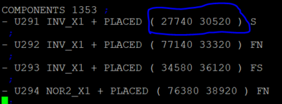
i have generated a layout using Cadence innovus and i opened a .def file in which i went to "COMPONENTS" section to know the placement information of standard cell instances. There i found co-ordinates(x,y) for only one point. I am confuse how we will able to figure out exactly where the instances are placed with that only one point? I am also attaching screenshot of COMPONENTS section from .def file

i have generated a layout using Cadence innovus and i opened a .def file in which i went to "COMPONENTS" section to know the placement information of standard cell instances. There i found co-ordinates(x,y) for only one point. I am confuse how we will able to figure out exactly where the instances are placed with that only one point? I am also attaching screenshot of COMPONENTS section from .def file