Continue to Site

Welcome to EDAboard.com

Welcome to our site! EDAboard.com is an international Electronics Discussion Forum focused on EDA software, circuits, schematics, books, theory, papers, asic, pld, 8051, DSP, Network, RF, Analog Design, PCB, Service Manuals... and a whole lot more! To participate you need to register. Registration is free. Click here to register now.

How to increase bandwidth of printed yagi antenna?

Status
Not open for further replies.

turuk

Junior Member level 3
Joined
Aug 30, 2019
Messages
29
Helped
0
Reputation
0
Reaction score
1
Trophy points
1
Activity points
224
Hi,
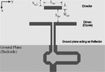
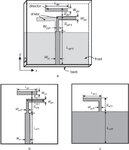
Ive designed a printed yagi with the MSC to CPS balun. I put the images of antenna and sparameter result. I want to pull down the band around 1-2 GHz to (-10) dB also. The problem is no matter which part of the antenna configuration ive changed, it always affects the band around 3GHz. The substrate lenght is 50x65mm. Any help will be appreciated.

antennafront.png
antennaback.png
antennasparam.png
 

Printed log periodic antenna ?


Regards, Dana.
 
Hi,

Can you explain to me your Yagi-Uda antenna, pls? I didn't see the driven elements, the reflector, and your dipole antenna.
Did you check the phase diff between the 2 poles of your antenna? The gain of your antenna is positive? What is the polarization of your antenna?

There are several technologies to increase the bandwidth of your dipole: use the parasitic elements, use a bowtie dipole, fractal antenna, use a high loss substrate, use a very thin substrate, etc. I'm not sure that a balun can help you broaden your bandwidth, it is used normally to match the impedance discretely.
 
Maybe is not shown everything in the initial picture, but this is an old printed Yagi design.
As any other Yagi antenna, you can build with or without the director element, in case you don't need increased directivity in a particular direction.
There is not much to do to get a tremendous increase of bandwidth of this antenna, if keep the elements as they are.
 

Attachments

  • yagi.jpg
    yagi.jpg
    23.2 KB · Views: 181

Printed log periodic antenna ?


Regards, Dana.
I added the log periodic eelments as director and the sparameter in 3dB got better but still not the one around 1GHz.
--- Updated ---

There are two components in this printed Yagi design that are bandwidth limited.
First, is the printed BALUN itself, which use a folded λ/2 element.
Second, is the driven element of the Yagi, which is a λ/2 dipole antenna.

An option to increase the bandwidth, is to change the driven element with a Bowtie dipole, but still the printed balun will limit the bandwidth.
Thank u so much for the reply. Im aware of that the dipole element restricts the bandwidth but is there any option other than changing the dipole element and balun type?( cuz this is a project and we already proposed it to be printed yagi) like playing with the dimensions are helping but not significant change can be observed.
--- Updated ---

Hi,

Can you explain to me your Yagi-Uda antenna, pls? I didn't see the driven elements, the reflector, and your dipole antenna.
Did you check the phase diff between the 2 poles of your antenna? The gain of your antenna is positive? What is the polarization of your antenna?

There are several technologies to increase the bandwidth of your dipole: use the parasitic elements, use a bowtie dipole, fractal antenna, use a high loss substrate, use a very thin substrate, etc. I'm not sure that a balun can help you broaden your bandwidth, it is used normally to match the impedance discretely.
Yes gain is positive in both resonant freq; but very low for 1.1 GHz which is 0.036 and for 3.1 GHz 4.76 dBi. How can i check the phase diff? By the way, It must be linear polarization if im not wrong.
 
Last edited:

It seems that your dipole works at 3 GHz. For the lower frequencies, you could add the parasitic elements to each arm of your antenna to have the other resonant frequencies. Try to improve also the gain at 1 GHz to ensure that your antenna can work in reality.
To know the polarization of antenna, you check its axial ratio.
I'm not sure that CST can check the phase diff of dipole, you can try Momentum ADS.
 

I added the log periodic elements as director and the sparameter in 3dB got better but still not the one around 1GHz.
An LPA has multiple driven elements, not directors. 1:2 bandwidth is however still in the range of yagi with single driven element, UHF TV antennas had a similar bandwidth.

I would replace the TL balun by transformer to separate it's effect from antenna behavior.
 
An LPA has multiple driven elements, not directors. 1:2 bandwidth is however still in the range of yagi with single driven element, UHF TV antennas had a similar bandwidth.

I would replace the TL balun by transformer to separate it's effect from antenna behavior.
Thank u so much for your reply it helps a lot. But I have couple of questions, Can i not use the directors shape as the log periodic desgin? I saw some papers do that and they not connected to the driven element. I mean is it something illogical? Another thing, TL balun is something like the image below? Since I dont have much experience about antenna design, i couldnt get what u mean by "TL balun by transformer to separate it's effect from antenna behavior." If u give any example it would be great
 

Attachments

  • Geometry-of-modified-printed-Yagi-antenna-a-3D-schematic-diagram-b-Top-layer-c-Bottom_W640.jpg
    Geometry-of-modified-printed-Yagi-antenna-a-3D-schematic-diagram-b-Top-layer-c-Bottom_W640.jpg
    38.8 KB · Views: 115

No, is not. Yagi antenna use one reflector (simple or various shapes), one driven element (usually a dipole), and one or multi-directors (sometimes with no directors at all). The best arrangement of the Yagi elements (lengths and spacings) is given by dedicated modeling programs.
 

Status
Not open for further replies.

Part and Inventory Search

Welcome to EDABoard.com

Sponsor

Back
Top