Continue to Site

Welcome to EDAboard.com

Welcome to our site! EDAboard.com is an international Electronics Discussion Forum focused on EDA software, circuits, schematics, books, theory, papers, asic, pld, 8051, DSP, Network, RF, Analog Design, PCB, Service Manuals... and a whole lot more! To participate you need to register. Registration is free. Click here to register now.

How to increase amplitude of output voltage from 100 m V to 1V

Status
Not open for further replies.

Neyolight

Full Member level 5
Joined
Aug 29, 2011
Messages
306
Helped
3
Reputation
6
Reaction score
3
Trophy points
1,298
Location
World
Activity points
3,624
Hi all

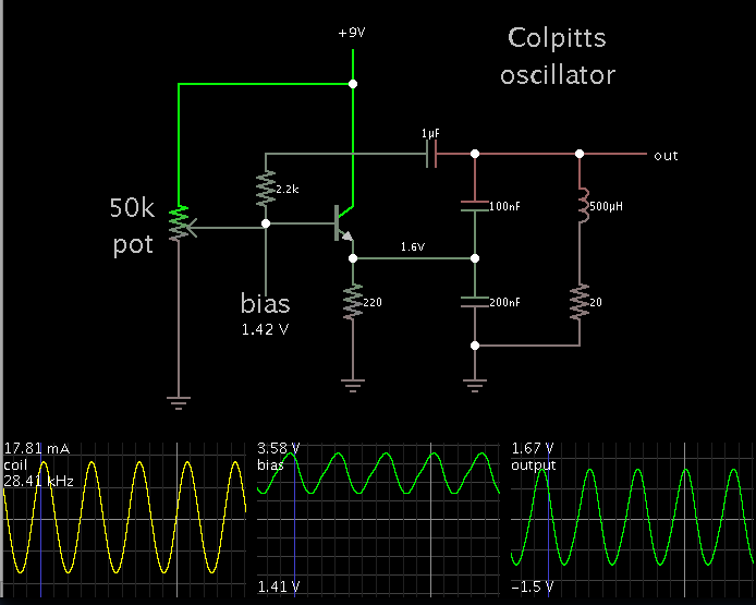
I am building a colpitts oscillator which seems to work just fine. The problem is its "vout" ( shown in the image) is a 100 mV sine wave with a frequency of about 60Khz. I need to square up this sine wave and using another transistor to do so.

At the moment , the second transistor is not turning on as the vout ( that is being fed to its base) is too low at 100mV. Could someone tell me a way to increase the amplitude of the Vout.

Thanks !
Neyo Oscillator.png
 

Your output transistor has no base bias voltage and the input signal level is too small to turn it on.
If it is biased properly then it will be an amplifier.
 
Your output transistor has no base bias voltage and the input signal level is too small to turn it on.
If it is biased properly then it will be an amplifier.

True but how do I change 100mV to something that will turn on my second transistor
 

Google 'common emitter amplifier'. That's what you need to know.
 
Oscillations will be much stronger if you reduce resistor values inline with the transistor.

Additionally, feed a small portion of oscillation waveform to the transistor bias.

Screenshot:

 
True but how do I change 100mV to something that will turn on my second transistor

I suppose, your oscillator provides a sinusoidal signal which you want to amplify.
Thus, you have to design the 2nd stage as a LINEAR amplifier - and there will be no "turn-on" effect.
In contrary, the bias network for the 2nd stage keeps this transistor always "turned-on" and the current through this transistor as well as the otput voltage vary around this bias point.
More over, use an emitter resistor for stabilizing the dc current (and thus, the bias point).
 

If the second transistor is properly biased then it could have a voltage gain of at least 150 times. Then the 100mV is its input and its output will try to be 15V so it will be clipping.
 
I dont know why anyone would go through all that trouble to create a square wave, but here it is, enjoy.
 

Attachments

  • SineToSquare.PNG
    SineToSquare.PNG
    52.1 KB · Views: 133

A single transistor has such high distortion at high levels that it makes a very poor square-wave even when it is biased properly.
 

Attachments

  • transistor squarewave.png
    transistor squarewave.png
    48.9 KB · Views: 170

It would be a lot easier with far less parts to just to use an LM339 comparator to convert the sinewave to a square-wave.
 
...or just generate a square wave in the first place e.g with an NE555.
 

It would be a lot easier with far less parts to just to use an LM339 comparator to convert the sinewave to a square-wave.
An LM339 has four comparators in a 14-pins package. But an LM393 has only two of the same comparators in an 8-pins package. I didn't look at the costs.
 

Only two transistors, four resistors and two capacitors are enough to make a circuit which will generate square wave at 60kHz and with amplitude of 9Vpp. Guess how.
 

Or 3 transistors, 1 capacitor and 6 resistors
 

Thanks all for replying. I am still kind of confused. The purpose is not just to create square wave but to convert the 'sine wave from the oscillator' to a square wave.

I am just depressed as when I look at an electronic circuit ( especially with a transistor or an opamp) all the comes up in my mind is "?". I wish I could understand a circuit like you all.
 

To convert a sinewave to a squarewave then you simply amplify the heck out of the sinewave so the amplifier output clips like crazy. An amplifier that is clipping produces a squarewave.
Since your sinewave is at a level that is lower than the minimum input threshold of a transistor then the base of the transistor must be biased properly and have the sinewave input capacitor-coupled to it.

The squaring circuit with two transistors in post #10 has the first transistor biased with a resistor from its collector to its base and is capacitor-coupled from the sinewave signal. The second transistor amplifies the output of the first transistor.
 
Ok I think I am beginning to get it. Just one question , what does this term mean "transistor bias" ?
 

A properly biased Transistor must have the ability not distort an input signal at the output, transistors have a lower limit of input voltage before it shows up at the output which is determined by the base emitter voltage. so by biasing, you have to put the base at higher voltage than the emitter in order to see your input signal at the output with both the negative and positive input swings.
 

Status
Not open for further replies.

Part and Inventory Search

Welcome to EDABoard.com

Sponsor

Back
Top