Continue to Site

Welcome to EDAboard.com

Welcome to our site! EDAboard.com is an international Electronics Discussion Forum focused on EDA software, circuits, schematics, books, theory, papers, asic, pld, 8051, DSP, Network, RF, Analog Design, PCB, Service Manuals... and a whole lot more! To participate you need to register. Registration is free. Click here to register now.

How to improve the PSRR of this circuit

Status
Not open for further replies.

walker5678

Full Member level 3
Joined
May 17, 2006
Messages
179
Helped
7
Reputation
14
Reaction score
3
Trophy points
1,298
Activity points
2,493
the diagram is an audio amplifier system which use BTL connection method.

If there is 217Hz ripple on the VDD, then the positive input terminal of the two amplifiers will also has ripple, which will induce the differential output voltage on Vo1 and Vo2.

How to improve the PSRR performance that makes Vo1-Vo2 minimum when there is 217Hz VDD ripple? except to increase the 1uF capacitor. ( the audio input terminal was short to ground for testing PSRR)
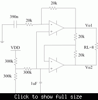
 
Last edited by a moderator:

You are difficult to improve the PSRR or CMRR of such config. Since the VDD are in the input signal. The ripple only divided by 2 and go inside the system.
 

walker5678 said:
... except to increase the 1uF capacitor.
Did you try a big cap from the 300k - 300k connection point to GND?
 

yes, the smaller the ripple on the positive input of the amplifier, the better the PSRR. so is there a way to make the positive input of the amplifier totally not affected by the VDD ripple? It just need a VDD/2 bias point.
And since 217Hz is a very low frequency, so the resistor and capacitor need to be very large to filter the ripple, which is hard to implement.
 

walker5678 said:
It just need a VDD/2 bias point.
And since 217Hz is a very low frequency, so the resistor and capacitor need to be very large to filter the ripple, which is hard to implement.
  • If the input current of your opAmp is low enough, you could use higher-valued resistors.
  • You could use 2 RC filters in series: one cap at the VDD/2 node, another one at the opAmp non-inverting input.
  • If the interfering frequency (217Hz) is actually very constant, you could use a notch filter against this frequency.
 

yes, i agree with the ways mentioned. However, the problem is, it is difficult to implement in IC.

For example, if add a 10pF capacitor at the VDD/2 node, and the resistor deviding VDD is 1M, so the cutoff frequency is 1/(500K*10p)*2*pi, which is 31K, which is far higher than 217Hz.

and it is the same for a notch filter.
 

Right. Then I can only think of the foll. possibilities:
  • Spend an additional pin for an external C to GND
  • Spend a BGA to make use of its very high PSRR
  • Find a method to introduce the same interference on both inputs of the opAmps in order to make use of their CMRR
 

If there is a way to build a DC bias voltage which is equal to VDD/2, and not affected by VDD variation, the PSRR will improve obviously.

Is there such a way?
 

Do low pass filter at the VDD/2.
If possible, add a pin and connect an external big cap.
Or, if possible use big resistor.
Or, is possible, use a active filter low bandwidth that passive filter doesn't work.
 

Or, is possible, use a active filter low bandwidth that passive filter doesn't work.

I am intrested in this. Can an active filter achieve cutoff frequency which is very low(below 217Hz), while only use capacitors in pF level? Can we utilize the miller effect to make this happen?
 

Status
Not open for further replies.

Part and Inventory Search

Welcome to EDABoard.com

Sponsor

Back
Top