alias0823
Junior Member level 1
how to improve load regulation
Hi all
When I design a buffer for voltage reference
There is a spec called transient load regulation
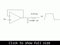
Its test circuit is as picture

Vin="Vsupply/2"; and Vtl transient from "Vsupply" to "0" and "0" to "Vsupply" within 0.1usec. Then I can monitor the voltage of Buffer output with a voltage peak.
My buffer design is a two stage amplifier, and I try two compensation method.
One is pole split method with miller compensation, and another is cascode miller compensation.
My question is how to improve transient load regulation? it means smaller voltage peak at buffer output.
Thanks
Added after 7 minutes:
Sorry, R=1k ohm.
Hi all
When I design a buffer for voltage reference
There is a spec called transient load regulation
Its test circuit is as picture

Vin="Vsupply/2"; and Vtl transient from "Vsupply" to "0" and "0" to "Vsupply" within 0.1usec. Then I can monitor the voltage of Buffer output with a voltage peak.
My buffer design is a two stage amplifier, and I try two compensation method.
One is pole split method with miller compensation, and another is cascode miller compensation.
My question is how to improve transient load regulation? it means smaller voltage peak at buffer output.
Thanks
Added after 7 minutes:
Sorry, R=1k ohm.