Welcome to our site! EDAboard.com is an international Electronics Discussion Forum focused on EDA software, circuits, schematics, books, theory, papers, asic, pld, 8051, DSP, Network, RF, Analog Design, PCB, Service Manuals... and a whole lot more! To participate you need to register. Registration is free. Click here to register now.
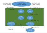
Connecting DIG_GND and RF_GND in a such a way is not appropriate.They should have been tied together at a common point on EARTH_GND.
So star configuration should be applied.Digital common mode signals will heavily disturb the RF circuitry. On the other hand RF signals' return path will also disturb the digital part ( less important ). Layout should be carefully examined..
Hi, thanks, Bigboss.
And the following picture is from the datasheet of a vendor,
P1 is the input of RS485, so the RS485 links to earth ground by a shunting R1 || C2, R1=1M Ohms, C2 is a capacitor with 1nF 2KV.
So I think it's right, the earth ground is dirty, such link can clean the ground.
When lighting, C2 is shunting, so protect other circuits.
And the input gnd are protected, then link the analog GND through RSM485 and SP00S12.
Any comment?
thanks
This site uses cookies to help personalise content, tailor your experience and to keep you logged in if you register.
By continuing to use this site, you are consenting to our use of cookies.