Continue to Site

Welcome to EDAboard.com

Welcome to our site! EDAboard.com is an international Electronics Discussion Forum focused on EDA software, circuits, schematics, books, theory, papers, asic, pld, 8051, DSP, Network, RF, Analog Design, PCB, Service Manuals... and a whole lot more! To participate you need to register. Registration is free. Click here to register now.

How to get the equation or corelaation of AC and DC

Status
Not open for further replies.

moonnightingale

Full Member level 6
Joined
Sep 17, 2009
Messages
362
Helped
5
Reputation
10
Reaction score
5
Trophy points
1,298
Activity points
3,832
How to get the equation or corelaation of AC and DC in Proteus

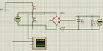
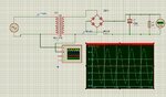
I have made the circuit in which AC is being converted to DC voltage from 0-5 Volts

Now this DC will be fed to MCU and based on this DC Voltage, the MCU have to Calculate the amplitude of AC voltage and from this amplitude of AC voltage further calculatations will be done

Now my question is this that is there any equation or method by which i can correlate the DC of this circuit with AC input in proteus
so that i can tell this equation to MCU and he will subsequently fiind AC
 

Attachments

  • SignalCond.jpg
    SignalCond.jpg
    212.3 KB · Views: 85
Last edited:

In a first estimation, the DC output voltage will be Vpeak - 2 * diode forward voltage. Vpeak is Vrms * √2, a diode voltage drop is about 0.7 V.

The problem get more complicated when considering transformer resistance and leak inductance, which can't be ignored particularly for a small transformer. I guess, you won't know the exact impedance parameters of your transformer, so an empirical calibration will be more accurate than a calculation.

As a general comment, it's usually unwanted for AC voltage measurement to have an output according to the input peak voltage which can abberate from RMS or averaged rectified value in case of a distorted waveform.
 

ok if i remove transformer and use voltage divider, will that simplify the equation
 

Can i get the transfer function of this circuit ??
 

The circuit is attached
I just removed the transformer and replaced it with voltage divider

But now result of voltage divider are strange
When there was no Recitifer, i used to get AC volts from +2.5 to -2.5
but now only from -1 to 1

is this effect due to rectifier
secondly can anybody tell me transfer function of this circuit

And what will be the impact of frequency of AC input
Lets suppose initially frequency is 20 Hz and later on it becomes 80 Hz

How it will impact the circuit.. will it effect impedance of capacitor???
 

Attachments

  • transformerless.jpg
    transformerless.jpg
    143.7 KB · Views: 116
Last edited:

I suggest to omit R2, then you get averaged rectified value of the input voltage multiplied with R1/(R1+R3). The rectifier voltage drop is reduced to a very small remainder. Averaged value is √2*2/3 Vrms.
 

Status
Not open for further replies.

Part and Inventory Search

Welcome to EDABoard.com

Sponsor

Back
Top