Continue to Site

Welcome to EDAboard.com

Welcome to our site! EDAboard.com is an international Electronics Discussion Forum focused on EDA software, circuits, schematics, books, theory, papers, asic, pld, 8051, DSP, Network, RF, Analog Design, PCB, Service Manuals... and a whole lot more! To participate you need to register. Registration is free. Click here to register now.

[SOLVED] How to get rid of another resonance in 2.4 GHz rectangular patch antenna?

Status
Not open for further replies.

Hana Rashid

Newbie level 5
Joined
Jun 18, 2014
Messages
10
Helped
0
Reputation
0
Reaction score
0
Trophy points
1
Activity points
84
Hi all,

Need your tips n advise on my design.

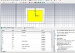
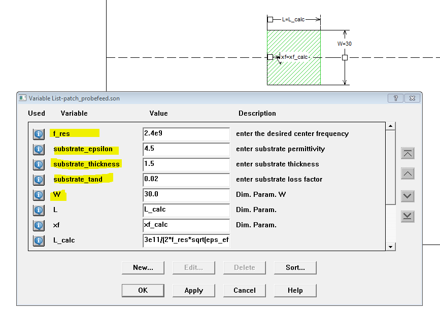
It is a 2.4GHz rectangular patch antenna, inset feed, FR-4 of er=4.3 and loss tangent 0.02. Simulate using CST MWR.
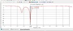
It shows double resonant in the S-11 parameter.
How does this happen? Is something wrong with my design? Which part of it that gets wrong?
What cause this to happen?
I don't know. Please help. Is there anywhere I could read about this? Any papers/books?
N which parameter I should adjust to get rid of those unwanted resonant?
I only want it to be at 2.4GHz.

the design, paramaters and s-11 are attached.
Thanks in advance.
 

Attachments

  • patch2.4_2jul14_3.jpg
    patch2.4_2jul14_3.jpg
    199.5 KB · Views: 114
  • patch2.4_2jul14_3_s11.jpg
    patch2.4_2jul14_3_s11.jpg
    146.8 KB · Views: 122

Maybe your s-parameters includes feeding line... I think there is a way to define s11 measurement point on feeding point inside patch.

update: also i checked my design in sonnet, i have similar maximums. I suggest that feeding position is not exactly at the symmetry point of patch (meshing?)
 
Last edited:
N which parameter I should adjust to get rid of those unwanted resonant?
I only want it to be at 2.4GHz.

To understand the extra resonance, look at the current visualization. But why do you care? Additional resonance don't cause any problem.
 
Maybe your s-parameters includes feeding line... I think there is a way to define s11 measurement point on feeding point inside patch.

update: also i checked my design in sonnet, i have similar maximums. I suggest that feeding position is not exactly at the symmetry point of patch (meshing?)

Terminator3 could you please elaborate more on that? Is it something to do with my wave-guide port setting? patch2.4_2jul14_3_waveguideport.jpg
 

The fake resonance is fatal for antenna, you can change grounding etc. to diminish it.
 

This is an inset feed patch antenna, and the "gap" is part of the matching. Nothing wrong with that.


,,, then, he must make resizing...!!!
,,, he must see that...**broken link removed**
 
Last edited:

The fake resonance is fatal for antenna
Why, particularly?

A rectangular patch can be expected to show multiple resonances related to different modes. A more interesting question would be e.g. if the antenna achieves the intended directional characteristic at the designed frequency, or if the bandwidth is sufficient.
 
Last edited:
What are those simulation programs on the pictures?
 

I want ask some question. On a thick substrates i can't get good S11 when adding feeding line and matching line. Patch without feeding is perfect. Anybody know why is that? I think because line width
vs impedance change is too rapid, and there are some ugly reflections at lambda/4 matching part vs 50 ohm line. Simulated 2.4 and 5ghz patches, substrate 1.6mm. No such problems on 0.8mm

,,, on a thin substrate, are other dimensions, compared to a thicker substrate...!!!

,,,for Hana...
 

Attachments

  • patch 2442mhz_07.jpg
    patch 2442mhz_07.jpg
    28.2 KB · Views: 129

    V

    Points: 2
    Helpful Answer Positive Rating
On a thick substrates i can't get good S11 when adding feeding line and matching line. Patch without feeding is perfect. Anybody know why is that?

Patch antennas on 1.6mm substrate can be designed with good match. Actually, the thicker substrates helps. Without knowing what you have modelled, it is not possible to answer your question. Please upload your Sonnet model.

- - - Updated - - -

Here is a Sonnet model for a probe feed (not insert feed) patch antenna. Based on textbook equations, this automatically calculates (estimates) the patch length and feed point, based on the variables for frequency and substrate parameters. This estimate is a nice starting point. The only dimension variable set manually is the width. Sonnet *.son in the attached ZIP file.


I have not yet created something similar for inset feed, so you would need parameter sweep to optimize the inset length.
 

Attachments

  • patch_probefeed.zip
    1.3 KB · Views: 107
volker@muehlhaus, tried your project. Very interesting, i can learn from it about variables. I like put formulas, but do it all in external program called SpeqMath.
Maybe i did something wrong, because center frequency was a little higher after i used simulation. Tried 10.5GHz patch on Er=2.6 substrate with 0.5 height. Made patch width = height. Going to check it again after work.
 

Status
Not open for further replies.

Part and Inventory Search

Welcome to EDABoard.com

Sponsor

Back
Top