Continue to Site

Welcome to EDAboard.com

Welcome to our site! EDAboard.com is an international Electronics Discussion Forum focused on EDA software, circuits, schematics, books, theory, papers, asic, pld, 8051, DSP, Network, RF, Analog Design, PCB, Service Manuals... and a whole lot more! To participate you need to register. Registration is free. Click here to register now.

How to get microcontroller to drive gate of mosfet for SMPS

Status
Not open for further replies.

pc9460

Junior Member level 3
Joined
Jul 16, 2015
Messages
27
Helped
0
Reputation
0
Reaction score
0
Trophy points
1
Activity points
214
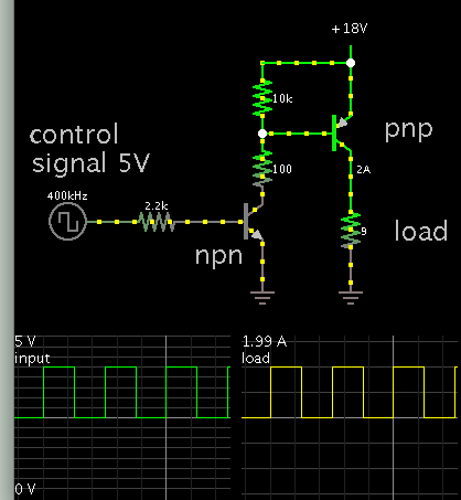
I got my simulation to work on multisim but would need to build the actual smps. The microcontroller I'm using is only capable of outputting 5V. I would need it to be 18V like it works at in my simulation. Is there a way to get the voltage up so it can drive the gate of my mosfet? I've thought about using a gate driver ic but don't know what to buy. Please give me some ideas. Thanks
 

Attachments

  • SMPS1.JPG
    SMPS1.JPG
    111 KB · Views: 236

A darlington arrangement may be what you need.

Consider adding an H-bridge biasing arrangement, for the purpose of causing the mosfet to switch on and off more abruptly.
 

Without knowing your intended output voltage, nor the
bridge rectifier's output, picking a suitable MOSFET
driver is problematic. However since you look to be
making a simple buck, with the high side a source
follower, I'd recommend one of the many half-bridge
driver ICs (like IR2110, but look around) and use the
high side output. You will need a bootstrap capacitor
and diode as well. App notes are plentiful and can
give you a "cookbook" power stage.
 

I'm trying to make a smps that outputs 5v dc and capable of 2amps. I just can't seem to find out how to get the pic chip to do the pwm since the one I'm using is only capable of 5v. I need 18v to get the mosfet to switch.
 

use a mosfet gate driver ic......you have to give it a supply equivalent to the voltage at which you want it to switch...and filter it well as gate drive pulses are high di/dt

heres a nice gate driver
https://www.edaboard.com/threads/341921/

but also non isolated ones do the job well, eg the **4427** family , which I think microchip do.

see "Laszlo balogh's" article on high speed mosfet gate drive to see all the ways fets can be driven.....but just go to digikey and search if you want to see whats on the market......literally type "mosfet driver" into digikey...however, it might be under "gate driver" or similar etc etc......if not try "FET driver"
 

I wonder which gate driver ICs you suggest for a buck converter with NMOSFET?

TC4427 e.g. won't do. The isolated Infineon driver, yes, but only with a separate driver power supply.

It must be a bootstrap driver to generate a gate voltage above Vin. And it needs an auxilary oscillator to charge the bootstrap capacitor if the output is not switching, or a similar means. Alternatively an isolated gate driver with separate power supply.
 

My only problem what the gate driver is that I have to provide equivalent voltage in to achieve the desired 18v out. Where would I get the required voltage to power the gate driver without getting a separate power supply for it?

Is there a way to get the mosfet to switch without using a gate driver? Like have an additional little circuit like a darlington configuration suggested above?
 

Is there a way to get the mosfet to switch without using a gate driver? Like have an additional little circuit like a darlington configuration suggested above?

This screenshot shows a 5V signal controlling an NPN transistor. The bias is only a few mA.

The NPN in turn controls a PNP.


The transistors are what is called a sziklai pair. It is similar to a darlington arrangement, except that a sziklai pair mixes N and P devices.

The 10k resistor is not absolutely needed for a transistor, however it is recommended for a P-mosfet in order to turn it off fully.

It is convenient to drive a P device this way. I placed it at the upper side, in the same position that your schematic has your switching device.

I see that you have 18V on the top of your circuit. My only problem with a gate driver is how to supply it 18V so it outputs 18V to the gate of my mosfet. I think with your circuit I still have the same problem with getting the required voltage..
 

My only problem with a gate driver is how to supply it 18V so it outputs 18V to the gate of my mosfet. I think with your circuit I still have the same problem with getting the required voltage..
Yes, that's true. Possible options are:

- using a bootstrap circuit, involves some restrictions regarding duty cycle and startup
- using a PMOSFET
- using an isolated power supply or charge pump to generate the required gate voltage on top of the input voltage.
- a combination of 1 + 3, bootstrap driver with low power charge punp to support 100 % duty cycle and easy startup
 

Is there a way to do the pwm without a microcontroller? I've heard of a way to do it with a gate driver and some sort of feedback controller (PID i think it was called)?
 

you can also use gate drive transformer to drive fet through, to stop you needing extra supply.
 

you can also use gate drive transformer to drive fet through, to stop you needing extra supply.

How does the gate driver transformer work? Do I still need the pwm input like from a microcontroller? I've never heard of it.
 

yes you still need a pretty juicy input, from a low impedance source, at the end of the day, you cannot drive fets on and off from a micro pin alons, unless its a very low power smps. Laszlo Balogh article have the gate drive transformer for you..

http://www.radio-sensors.se/download/gate-driver2.pdf

page 30 onwards
 
Last edited by a moderator:

Do I have the idea of how a gate driver works correctly? It will output the same input voltage so if I need 18V at the output of the gate driver I need to supply 18V to drive the gate of my mosfet according to my simulation. I honestly don't know much about them but would really appreciate you input!
 

An NPN transistor has its bias referenced to its more negative terminal (emitter). Similarly with an N-mosfet, its bias is referenced to its more negative terminal (source).

The bias needs to see a definite path to ground. Therefore it is easier if you place the N device close to ground, and put the load in the more positive leg.

To do the above, you could rearrange your entire circuit. Place the buck converter so it is close to the positive supply. Use an NPN transistor, because it is more familiar.

To turn on an NPN, you do not have to apply more than 0.7V to the bias terminal. Mosfets on the other hand, have some uncertainties about what level voltage you need to apply to the bias.

You can avoid rearranging your entire buck converter if you were to use a PNP transistor. Its bias is referenced to its more positive terminal. To operate it, you connect the bias to the positive supply, or connect it to ground (to give a simplified explanation). An NPN acts as a middleman to make the job easy. My post #9 shows how to build it. It will work whether the power supply is 18V, or any other voltage.
 

If I used a gate driver like the TPS2811 would that work? Would it work with me supplying 5V dc and controlling it with my microcontroller? It seems to work on multisim but I need to do some type of feedback circuitry to keep the output voltage of my smps 5V dc. Any ideas? I would be open to ditching the microcontroller and trying to design some feedback circuitry to make it easier.Capture.JPG
 

I would be open to ditching the microcontroller and trying to design some feedback circuitry to make it easier.

An op amp can work as a simple controller.


I have tested this concept in hardware, at very low volt and Ampere levels.

The op amp is powered by the 18V supply. Its output voltage must go high enough to turn off the P-mosfet.
 

If I used a gate driver like the TPS2811 would that work?
TPS2811 is a low side driver and does not work (or more exactly, doesn't achieve correct switching) with a buck converter and NMOSFET switch. I believe you'll see this if you review the simulation results thoroughly.

The problem of controlling the power switch with a suitable circuit isn't directly related to the intended usage of a microcontroller. It also arises if you use a conventional PWM controller IC or any other switched mode regulator control design.

The microcontroller adds a digital controller design problem. If you feel that designing the power stage is demanding enough, changing to conventional analog control might be wise.
 

Status
Not open for further replies.

Similar threads

Part and Inventory Search

Welcome to EDABoard.com

Sponsor

Back
Top