Continue to Site

Welcome to EDAboard.com

Welcome to our site! EDAboard.com is an international Electronics Discussion Forum focused on EDA software, circuits, schematics, books, theory, papers, asic, pld, 8051, DSP, Network, RF, Analog Design, PCB, Service Manuals... and a whole lot more! To participate you need to register. Registration is free. Click here to register now.

How to get Desired Axial Ratio from Circular Polarized Patch?

Status
Not open for further replies.

Younker_899

Newbie level 6
Joined
Mar 3, 2012
Messages
14
Helped
0
Reputation
0
Reaction score
0
Trophy points
1,281
Activity points
1,364
I have designed Circularly polarized patch with matchind feed but my result doesnot give me correct axial ratio which is 20 so how can i reduce the axial ratio please help me..

thanks in advance.
Regards
JD
 

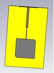
If you have an axial ratio of 20, you actually have a linear polarized antenna, as it should be 1 (0 dB) for a circular polarized antenna. What type of antenna and feed system do you have (you may post image)?
 
There seems to be problem with your matching feed. Make sure to create 90 deg phase diff. If you can share type of ant and feed may be some soln. can be found.
 

I Fed with a Quarter-Wavelength Transmission Line with truncated corners but i got Axial Ratio 20.

Regards
Junaid Iqbal ant.JPG
 

Corners are not truncated much. In order to get 90 phase shift, you need to truncate more to generate 2 separate X-Y resonant modes such that when fed between each axis you can get more circular quality with desirable axial ratio of 3dB. Consider truncate corners by 25% and feed off-center.
more general info but not 1/4wave **broken link removed**
**broken link removed** example of circular path, bottom feed.

Better design two orthogonal antenna with diversity switch to choose best.

Dear sir.

How percent i truncate the corner of patch?Will i compare the truncation with it's width or length?
Regards
 

I try my best but still i couldn't get desirable Axial Ratio? Please help me out that what can i do with that?

I will be thankful to you all.

Regards
Junaid Iqbal
 

Status
Not open for further replies.

Part and Inventory Search

Welcome to EDABoard.com

Sponsor

Back
Top