Continue to Site

Welcome to EDAboard.com

Welcome to our site! EDAboard.com is an international Electronics Discussion Forum focused on EDA software, circuits, schematics, books, theory, papers, asic, pld, 8051, DSP, Network, RF, Analog Design, PCB, Service Manuals... and a whole lot more! To participate you need to register. Registration is free. Click here to register now.

How to generate PWM?

Status
Not open for further replies.

DIGITRONIC

Member level 1
Joined
Sep 21, 2012
Messages
35
Helped
1
Reputation
2
Reaction score
1
Trophy points
1,288
Location
Darbhanga,Bihar,India
Activity points
1,488
Hi All,

I want to know about the abc of PWM. I have seen it in many Inverter & UPS circuits but my concept is not very much clear.Can anyone help me? I am using PIC16F72 & Mikro C compiler.

Thanks
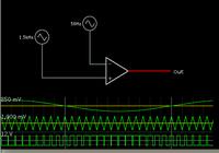
 

What do you already know about PWM? If you need to learn about the very basics, you should go through some tutorials such as:
https://forum.allaboutcircuits.com/showthread.php?t=44767
https://extremeelectronics.co.in/avr-tutorials/introduction-to-pwm-pulse-width-modulation/
https://www.8051projects.net/pulse-width-modulation/introduction.php

You can generate PWM in hardware or in software.

If you want to generate PWM in hardware, you can use the CCP module in the PIC16F72. You can use the PWM section of the CCP module, or you can also use the compare section of the CCP module.

Hope this helps.
Tahmid.
 
Last edited:

Hi All,

I want to know about the abc of PWM.

HI DIGITRONIC ..

If you want to know basics about PWM... you Must go for this link...

https://extremeelectronics.co.in/avr-tutorials/introduction-to-pwm-pulse-width-modulation/

if you understand this PWM signal generation will nothing for you...
also there is some great explanation on generation of the same using timer which is on these links but it is based on AVR...

https://extremeelectronics.co.in/avr-tutorials/pwm-signal-generation-by-using-avr-timers/

https://extremeelectronics.co.in/avr-tutorials/pwm-signal-generation-by-using-avr-timers-part-ii/

if you understand in this on AVR i think you will easily do in PIC and all also...

HOPE this will help...

Ismail
 

Use the timer module as the time base and use the compare module. I'm guessing you're going to generate a 50Hz output. You can't use the PWM part of the CCP module for that low a frequency without really lowering the oscillator frequency. That will just make code execution slower. So, it's better you use the compare module with a faster oscillator frequency.
 
how can someone use the compare module?
 

Dear Tahmid
you are right,but I want to know why 1.5khz needed?

Perhaps you are referring to the frequency of the triangle wave in my schematic (post #8)?

It doesn't have to be 1.5 kHz. I only experimented until I found a combination that brought out the distinctive appearance of the resulting waveform.

You can choose whatever frequency works best with your components.
 

The 1.5kHz is the carrier frequency. You'll come across it when using sinusoidal pulse width modulation (SPWM). Before that, you should practice and clearly understand basic PWM.
 

Two ways
1) Software method.
void pwm_function(pwn_value)
{ Set_bit_High;
delay(pwm_value);
set_bit_Low;
delay(100-pwm_value)
};

in above program , pwm_value is indicated in 100%.

2) Choose a microcontroller with internal PWM hardware
update the PWM registers.
 

Status
Not open for further replies.

Similar threads

Part and Inventory Search

Welcome to EDABoard.com

Sponsor

Back
Top