Continue to Site

Welcome to EDAboard.com

Welcome to our site! EDAboard.com is an international Electronics Discussion Forum focused on EDA software, circuits, schematics, books, theory, papers, asic, pld, 8051, DSP, Network, RF, Analog Design, PCB, Service Manuals... and a whole lot more! To participate you need to register. Registration is free. Click here to register now.

how to fix timestep error in proteus??

Status
Not open for further replies.

shivam sagar

Newbie
Joined
Jul 31, 2021
Messages
4
Helped
0
Reputation
0
Reaction score
0
Trophy points
1
Activity points
17
hello everyone , i am trying to simulate this IGBT driver circuit. but when i simulate it , i get timestep error.
how to fix this??
plzz tell
 

Attachments

  • Screenshot (211).png
    Screenshot (211).png
    35.2 KB · Views: 251

What's your frequency of operation? Whatever it is, set a timestep so between 100 and 1 million of them fit in one switching period.

Another thing to try is to put low-ohm resistors inline with capacitors, inductors, diodes. If there is zero resistance, the simulator is unable to calculate a time constant as RxC or L/R.
 

Sir, i tried both method provided by you , but still i m getting time step is too low.
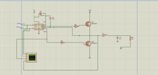
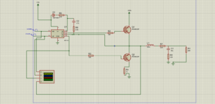
Is there any problem with my circuit ?? basically I am simulating an IGBT driver circuit, with RLC load.
 

Attachments

  • Screenshot (213).png
    Screenshot (213).png
    38.4 KB · Views: 149

1.
The node at R7 R1 C1 has no dot indicating a join. Elsewhere your schematic does have dots where 3 wires join.

2.
Wires below R6 have dots indicating joins in unexpected spots. Make sure there is no rogue wire overlapping other wires since the overlap mimics an optical illusion of continuous wire. Make sure wires that should be connected really are connected.

3.
Make sure the node between Q1 Q2 really has 4 wires joining.
 

This is a common problem as you can see from the list of similar threads further down this page. You may find a solution among those.

A common recommendation is to connect a high-ohm resistor from transistor bias to the emitter or source terminal. This sets the bias to a definite value as the run begins, so you do not have any floating inputs. (For N devices the source is the more negative terminal.)
 

hello , I am trying to code variable duty cycle PWM on PIC16F877A, desired frequency 2Khz, using Timer2 interrupts. But I am not getting PWM on oscilloscope .
please tell where i am doing mistake. (Code is written using MPlab)

Code:
#include <stdio.h>
#include <stdlib.h>
#include<xc.h>
#include "config.h"
#define _XTAL_FREQ 4000000 //4 MHz..


unsigned char count=0;

unsigned char sine[20]={ 0, 78, 155, 227, 294, 354, 405, 446, 476, 494, 500, 494, 476, 446, 405, 354, 294, 227, 155, 78};
void __interrupt()  my_ISR(void)
{   if(TMR2IF==1)
{
    count++;
    if(count>=20)
    {
        count=0;
    }
    CCPR1L=(sine[count]>>2);
    CCP1X=(sine[count]&2);
    CCP1Y=(sine[count]&1);
    TMR2IF=0;
    RB0=~RB0;
}
  
}


int main(int argc, char** argv) {
   CCP1M3 = 1;
  CCP1M2 = 1; // activating PWM mode..
  TRISC = 0; // The CCP1 Output Pin (PWM)
  // Set The Prescale For Timer2 (1:4 Ratio)
  TRISB0=0;
  RB0=1;
  T2CKPS0 = 1;
  T2CKPS1 = 0;
  PR2=124 ;//setting frequency for pwm, 2khz..
  TMR2=0;
    TMR2IF=0;
  GIE=1; // activating interrupts..
  PEIE=1;
  TMR2IE=1;

  TMR2ON=1;
  //CCPR1L=64;
  while(1)
  {
      // go on....
  }
 
 
    return 0;
}
--- Updated ---

hello everyone, I am trying to code variable duty cycle PWM on PIC16F877A, desired frequency 2Khz, using Timer2 interrupts. But I am not getting PWM on oscilloscope .
please tell where i am doing mistake. (Code is written using MPlab)


C:
#include <stdio.h>
#include <stdlib.h>
#include<xc.h>
#include "config.h"
#define _XTAL_FREQ 4000000 //4 MHz..
 

unsigned char count=0;

unsigned char sine[20]={ 0, 78, 155, 227, 294, 354, 405, 446, 476, 494, 500, 494, 476, 446, 405, 354, 294, 227, 155, 78};
void __interrupt()  my_ISR(void)
{   if(TMR2IF==1)
{
    count++;
    if(count>=20)
    {
        count=0;
    }
    CCPR1L=(sine[count]>>2);
    CCP1X=(sine[count]&2);
    CCP1Y=(sine[count]&1);
    TMR2IF=0;
    RB0=~RB0;
}
    
}

int main(int argc, char** argv) {
   CCP1M3 = 1;
  CCP1M2 = 1;     // activating PWM mode..
  TRISC = 0;        // The CCP1 Output Pin (PWM)
                       // Set The Prescale For Timer2 (1:4 Ratio)
  TRISB0=0;
  RB0=1;
  T2CKPS0 = 1;
  T2CKPS1 = 0;
  PR2=124 ;       //setting frequency for pwm, 2khz..
  TMR2=0;
    TMR2IF=0;
  GIE=1;            // activating interrupts..
  PEIE=1;
  TMR2IE=1;

  TMR2ON=1;
  while(1)
  {
      // go on....
  }
 
 
    return 0;
}
 
Last edited:

Status
Not open for further replies.

Similar threads

Part and Inventory Search

Welcome to EDABoard.com

Sponsor

Back
Top