Continue to Site

Welcome to EDAboard.com

Welcome to our site! EDAboard.com is an international Electronics Discussion Forum focused on EDA software, circuits, schematics, books, theory, papers, asic, pld, 8051, DSP, Network, RF, Analog Design, PCB, Service Manuals... and a whole lot more! To participate you need to register. Registration is free. Click here to register now.

[SOLVED] How to find the Zth of this circuit?

Status
Not open for further replies.
D

darrenbkl

Guest
impedance

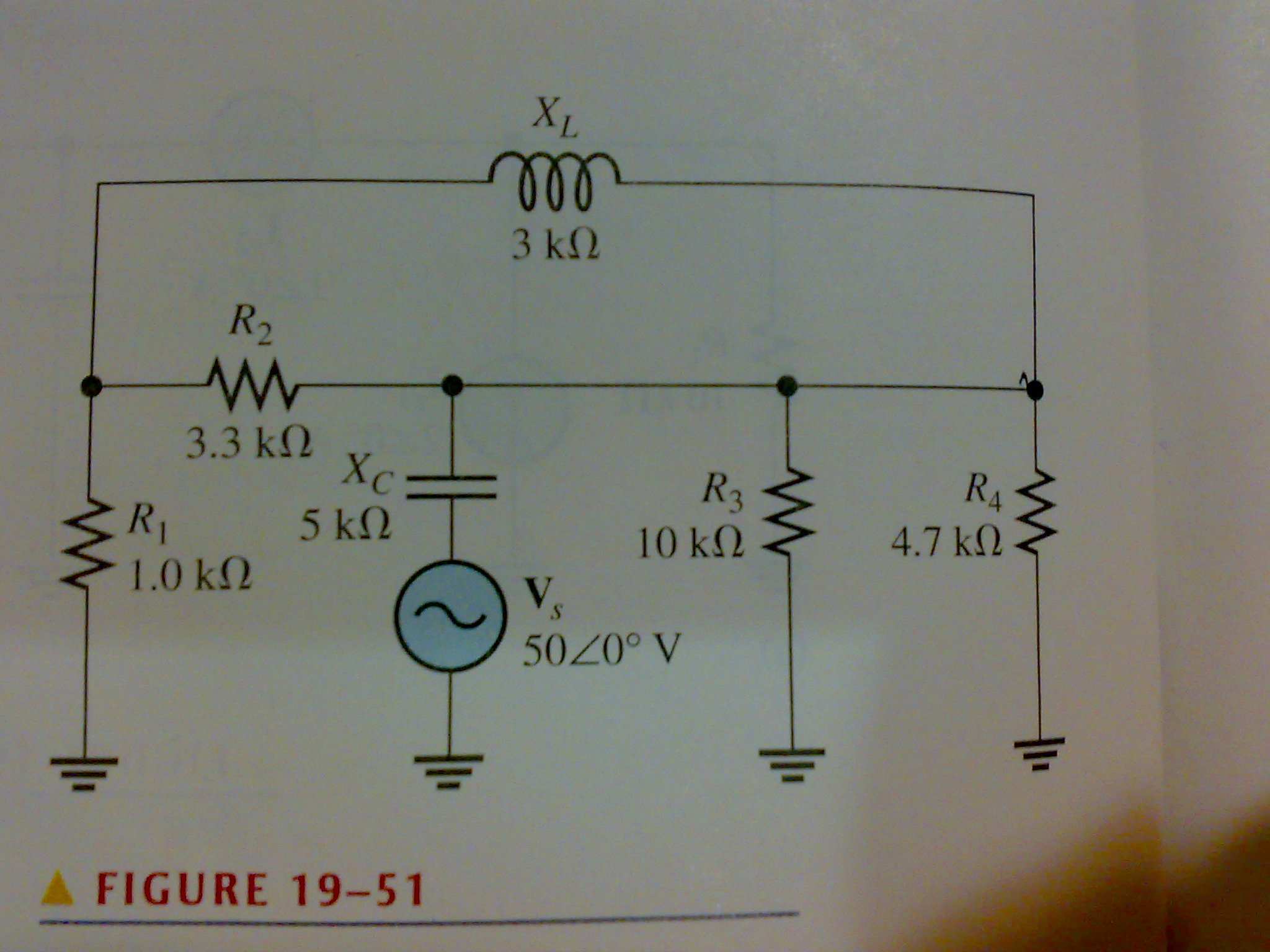
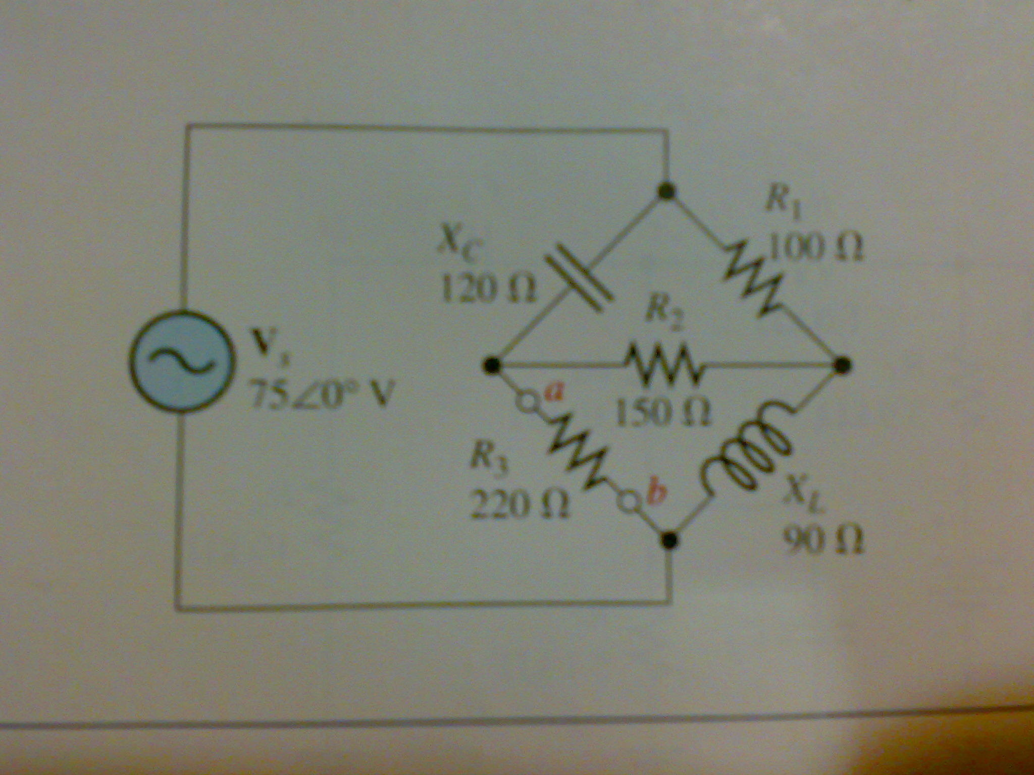
Hi , for this question, can anybody teach how to find the Zth of this circuit?
because of the L1, i dunno how to solve that,thx.
**broken link removed****broken link removed**
 

impedance

emm,I mean i want to find the thevenin equivalent impedance looking from the right side, can anybody solve tat for me?with complete working,thx very much
 

Re: impedance

Zth=R4//R3//(1/jwC2)//(R1+R2//jwL1)

Added after 40 seconds:

w=60Hz
 

Re: impedance

Please make the circuit diagram clear
 

impedance

You can use simulator ... For example multisim or proteus. Multisim is simpler.

If ur interested in calculation, you need to get formulas and equations. You may need a material to learn from.

Material:
http://www.ene.ttu.ee/leonardo/elektro_alused/

Itis in estonian but im pretty sure that if you want you will find what you are looking for..
 
  • Like
Reactions: ramz

    ramz

    Points: 2
    Helpful Answer Positive Rating
Re: impedance

Hi,

Whatever Saruman has written except ω=2Πf and not 60Hz.

Regards,
Laktronics
 

Re: impedance

Yeap. That's a classic mistake i always do. I keep omitting 2π when calculating impedance components (It has often led me to very wrong results, obviously).
 

Re: impedance (help me solve some problem) !!

I always confuse of the component that hang across the sky there,in this case is L1. so basically we paralled the component inside then only deal with outside right?

Added after 3 hours 17 minutes:

How about this two question,i know it is simple but i still cant figure it out.

1)Using Thevenin's Theorem,find the voltage across R4.


2)Simplify the circuit external to R3 to its Thevenin Equivalent.
 

Re: impedance

1)You must replace all of the circuit except the resistor R4 witn its thevenin equivalent, then the apply a voltage divider equation between R4 and the Zth of the rest circuit.

In this case,(with the voltage source short circuited) the Zth of the circuit neglecting R4 is:

Zth=R3//-jXC//(R1+jXL//R2)

In order to find the Vth one must open circuit the circuit left of R4 and calculate the voltage at the floating node as (Vs in normal operation):

Vth=Vs*(R3//(R1+jXL//R2))/(R3//(R1+jXL//R2)-jXC) (voltage divider too)

The voltage acrooss R4 is:

V4=Vth*R4/(R4+Zth)

Added after 10 minutes:

2)Again, short circuit Vs, then calculate the impedance seen from a,b as:

Zth=-jXC//(R2+jXL//R1)

As before, open circuit a,b (i.e. remove R3) and calculate the voltage Vab with Vs in normal operation (might need a little bit of calculations)
 

impedance

thx saruman for ur patient : )
about the bridge circuit,is there any rule associate with it?
 

Re: impedance

It would be pretty easy since with the removal of R3 there is no bridge at all from what concerns the thevenin equivalent. You can use 2-3 voltage divider equations to find Vth, finding VXL and VR2 and then adding them. In any case, if you are interested in calculating impedances of circuits containing bridge components, i think it would not be difficult either to find some examples or general relationships on google or wikipedia (i can't remember the relations right now).

Cheers,
vag
 

impedance

can anyone explain me how capacitor smooth out rectified voltage? I don't understand,in detail,how does the caps respond to the rectified dc voltage.

Does the smoothing cap must be electrolytic cap?
 

Status
Not open for further replies.

Part and Inventory Search

Welcome to EDABoard.com

Sponsor

Back
Top