Continue to Site

Welcome to EDAboard.com

Welcome to our site! EDAboard.com is an international Electronics Discussion Forum focused on EDA software, circuits, schematics, books, theory, papers, asic, pld, 8051, DSP, Network, RF, Analog Design, PCB, Service Manuals... and a whole lot more! To participate you need to register. Registration is free. Click here to register now.

How to Find Common Emitter, Base And Collector ? Configuration of Transistor Circuits

Status
Not open for further replies.

asking

Full Member level 5
Full Member level 5
Joined
Sep 21, 2010
Messages
279
Helped
6
Reputation
12
Reaction score
6
Trophy points
1,298
Activity points
3,377
Hello,

I have been trying to find how to find the circuit is having common collector circuit or common emitter or common base ? please gimme some hints...that would be helpful.... i know little that the thing which is common to both input and output is common (E,B or C) configuration. Please help me to find the configuration in the below circuit....
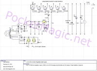
 

A transistor terminal can be identified as "common" if it's connected to a power supply node (ground or supply voltage) respectively a fixed potential. By this criterion, the circuit can be recognized as common collector.

As another simple point, the transistors are controlled through the base terminals, thus it's surely not a common base circuit.
 

Thanks....for information...

can anyone tell me.... me how the voltage part is controlled by LM317 and current is Controlled through Transistor ? Because as far as i know current is never alone Voltage is somewhere in the scene...then how come voltage is maintained by LM317 and current is increased by use of Pass Transistors ?

i m newbie...to this section so a little guide would be appreciated...
 

The LM317 uses negative feedback to adjust the output voltage to be a constant, independent of the output current. There is an internal reference voltage of 1.2V in the circuit. The circuit always tries to keep the voltage between the output and the control terminal equal to 1.2V. It internally adjusts the pass transistor drive to maintain this output voltage.

You add two resistors between the output and ground with the resistor junction connected to the control terminal to adjust the regulated output voltage. Again the circuit will adjust the output until the voltage drop from the resistive divider output is equal to 1.2V. For example, if the two resistors were equal in value, then the output voltage would be 2.4V to maintain the voltage between the output and the control terminal 1.2V.
 
  • Like
Reactions: asking

    asking

    Points: 2
    Helpful Answer Positive Rating
Status
Not open for further replies.

Similar threads

Part and Inventory Search

Welcome to EDABoard.com

Sponsor

Back
Top