Continue to Site

Welcome to EDAboard.com

Welcome to our site! EDAboard.com is an international Electronics Discussion Forum focused on EDA software, circuits, schematics, books, theory, papers, asic, pld, 8051, DSP, Network, RF, Analog Design, PCB, Service Manuals... and a whole lot more! To participate you need to register. Registration is free. Click here to register now.

How to filter Contactor and/or AC Motor noise from Microcontroller

Status
Not open for further replies.

signalflow

Newbie level 5
Joined
Nov 15, 2013
Messages
9
Helped
0
Reputation
0
Reaction score
0
Trophy points
1
Activity points
118
power supply.JPGHi, I am using a microcontroller to drive some relays that drive contactors. My board is powered by the 208Vac through transformer then through bridge then to LM2596 simple switcher which gives a 5.0V output. Then that 5.0V is sent through a LM3940 to generate 3.3V output needed for other chips. There is another contactor that is controlled by just a physical switch.

When I turn on the contactor (via the manual switch), noise comes back through the AC lines/transformer/bridge, etc. and resets my board (very often). The contactor isn't currently powering anything, so I'm just manually energizing the contactor coil.

I have a quencharc (snubber) on the contactor.

I also drive a relay that turns on an AC motor (fan). If I turn the fan on via the relay, then this will reset my board very often.

The only filtering I have on the board is a common-mode choke before the bridge rectifier. I do have 0.1uF bypass caps on every chip.

Can anyone suggest what the best or most common method to filter out this noise would be? I tried adding a low-pass filter just after the transformer (just before the common mode choke and bridge rectifier) but my electrolytic caps smoked very fast. It was an LC filter with a 100uF series inductor with a 6.8uF shunt capacitor. So not sure why my cap smoked either (maybe because they were electrolytic). Should I move the LC filter to after the bridge rectifier?

Thanks for help!
 
Last edited:

Your circuit has errors, the line that is marked +24V is AC? so NO electrolytic capacitors on this line. When you switch AC mains there is a lot of voltages flying about which need to be screened and kept under control. So the first thing is to make sure that the core of your 208V transformer is earthed. Then to try and reduce any dV/Dt s about the place so a snubber on every relay coil. Then as a final resort screening all these high voltage leads. Once you start to switch real currents then there could be a useful improvement by twisting wires that carry the same currents together so the current sourced magnetic fields cancel.
Frank
 

The chassis of the 208V transformer is tied to earth gnd.

Yes, that is 24Vac coming in. OK, so that's why the caps fried...electrolytic (thank you!). Well, I removed them after they fried, so the circuit that I have been testing only has the inductor (L4), common-mode choke, rectifier, and cap (C6) before going into the LM2596 and LM3940.

I have a snubber on the contactor coil (that is resetting the board very often). I also have a flyback diode across the relay that is driving the AC motor (fan) which is also resetting the board very often. The AC motor (fan) does not have snubbers across it.

So if I replace the electrolytic caps in the LC filter with ceramic caps after the 208Vac transformer, then should this filter out these transients generated by the contactor switching and AC Motor (fan) turning on?

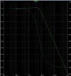
The frequency response of the LC filter has an fc @ ~ 7KHz. See attached. Will this filter out these transients? I just don't know the characteristics of the transients from these contactors and AC motor, I suppose.
LC filter - freq response.JPG

Thanks.

- - - Updated - - -

Well, I realized it's not so easy to replace the large electrolytic with ceramic equivalents. Should I move the LC filter to AFTER the rectifier and before the large smoothing cap (C6) so that I can use electrolytics in the LC filter since it is a DC voltage there?

- - - Updated - - -

I measured the voltage coming out of the transformer with an o-scope and set the trigger slightly higher than the normal waveform peak, so it would start saving data when I turned on the contactor.

Ch1 is one line of the transformer secondary and Ch2 is the other line of the transformer secondary. So Ch1-Ch2 is the difference between the two.

Looks like the noise is similar on Ch1 and Ch2, so must be common-mode noise. It doesn't show up much on the Ch1-Ch2 trace. I have a common-mode filter on my input, so not sure why this is getting through.

contactor turn on noise.JPG
 

Or should I just add a TVS (transient voltage suppressor) bi-directional diode before the common-mode choke?
 

Thanks, Golden Electronics. So just shortening the cable length to your LCD fixed your problem?

I know I need some type of filtering on board since large inductive loads are on the same power lines that feed the power supply of my board. I just don't know what the best method is. I can't really shorten my cable length to LCD (6" inches long).

My circuit works great on a bench with no large inductive loads switching. But once those large inductive loads are put on the power lines and turn on/off, I get scrambled LCD data.

I am about to order some TVS bi-directional diodes and put some before or after the common-mode choke and see if that helps.

- - - Updated - - -

Should I use bi-directional TVS diodes across AC input and uni-directional across DC power lines? Or could the GND of the DC power line have transient negative voltages so that I would need a bi-directional across the DC power lines as well?
 

Status
Not open for further replies.

Similar threads

Part and Inventory Search

Welcome to EDABoard.com

Sponsor

Back
Top