Welcome to our site! EDAboard.com is an international Electronics Discussion Forum focused on EDA software, circuits, schematics, books, theory, papers, asic, pld, 8051, DSP, Network, RF, Analog Design, PCB, Service Manuals... and a whole lot more! To participate you need to register. Registration is free. Click here to register now.
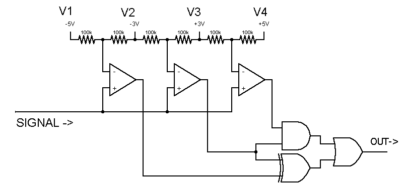
The gate logic could be done in software e.g. on a microcontroller instead, if necessary. Make sure to choose comparators with appropriate output levels for the gates / microcontroller / whatever.
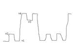
If you don't know V1, V2, V3, and V4 but you know the ratio between them and you know they'll remain roughly consistent you can use a similar circuit with capacitors to track the upper and lower input signal limits feeding voltage dividers for inputs to the comparators.
In both of the above circuits if the input slew rate is too low you will still get erroneous output during transitions (e.g transitioning from V2 to V4 will cross V3) so you may still have to do some output filtering (e.g. cap at output of https://tinyurl.com/bsqla5c).
If you know the frequency of the inputs a buffer -> highpass filter -> comparator could do the job although might be a little trickier to set up:
You might throw a small cap at the output to absorb noise.
- - - Updated - - -
I specified a broken link for the second circuit. It is fixed now.
- - - Updated - - -
Example using capacitors to track signal range; resistors determine threshold ratios within range: https://tinyurl.com/c53x2ut (also has output filter -- cap at input is just to generate input with low slew rate and is not part of circuit).
If the high frequency is a fixed frequency, you can run the signal through a band-pass filter and then output that to a comparator to convert it to a digital signal.
other methods:
1. use a PLL with lock-in range centered on the high frequency then gate it's output with the original signal.
2. sample the waveform and run a FFT analysis to find the dominant frequencies then recreate the desired one. This is a software solution but it will give both frequencies as it's result.
Thanks a lot for your help.
Actually v1~v4 might droop due to attenuation and isi in long cables. The high speed can be several Gbps and the slow one can be as low as several Kbps while they are coupled together on driver and receiver ends working simultaneously in full duplex mode.
For Jason's circuit, how could I cope with the varying comparison levels which will later transfers to jitters in the receiver? Also additional replica path and synchronization must be applied to remove the logic glitches.
Crutschow, since the data patterns are random, the bpf might not help here.
Betwixt, they have different levels and a cdr might be needed here.
This site uses cookies to help personalise content, tailor your experience and to keep you logged in if you register.
By continuing to use this site, you are consenting to our use of cookies.