Continue to Site

Welcome to EDAboard.com

Welcome to our site! EDAboard.com is an international Electronics Discussion Forum focused on EDA software, circuits, schematics, books, theory, papers, asic, pld, 8051, DSP, Network, RF, Analog Design, PCB, Service Manuals... and a whole lot more! To participate you need to register. Registration is free. Click here to register now.

How to estimate the on resistance of a switch

Status
Not open for further replies.

naalald

Full Member level 4
Joined
Dec 2, 2006
Messages
216
Helped
30
Reputation
54
Reaction score
5
Trophy points
1,298
Activity points
2,627
What do you suggest for estimating the on resistance of a switch? I think of giving a Vdd to its gate (for a simple NMOS or a transmission gate) and applying a pulse to its input. I put a capacitor Cload in the output; like this

6_1221565170.jpg


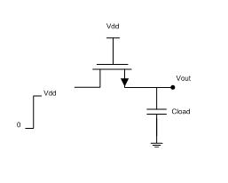
The output will follow the input exponentially with a time constant RC; C is the capacitor Cload and R will be the on resistance of the switch. By calculating the time constant, we can estimate the on resistance of the switch. How is the this test?
Any other suggestion?
Thanks.
 

The resistance (and capacitance) will vary quite a lot over such a big input step and it might become tricky to correctly define the resistance. Probably you might end up close to the answer. Also, when the input reaches supply you will effectively close the gate and then resistance suddenly becomes very large.

If you want the linearized AC resistance, gds will give you the answer and will probably be found in the simulation report file. Add a DC source and run an AC analysis for some different DC voltage - or sweep and plot 1/gds as function of DC voltage.

If you want the DC, large-signal resistance for different input voltages, you can simply add a voltage source on one side of the transistor, another voltage source on the other. Let the voltage difference be small, submV. Measure the current through the sources and calculate your deltaV/current = resistance. Plot that ratio as function of input DC voltage. I would suspect the answer to be quite similar to the gds approach.
 

Status
Not open for further replies.

Part and Inventory Search

Welcome to EDABoard.com

Sponsor

Back
Top