Continue to Site

Welcome to EDAboard.com

Welcome to our site! EDAboard.com is an international Electronics Discussion Forum focused on EDA software, circuits, schematics, books, theory, papers, asic, pld, 8051, DSP, Network, RF, Analog Design, PCB, Service Manuals... and a whole lot more! To participate you need to register. Registration is free. Click here to register now.

How to eliminate the oscillation of VGA ?

Status
Not open for further replies.

bigworm

Member level 3
Joined
Nov 13, 2004
Messages
62
Helped
1
Reputation
2
Reaction score
0
Trophy points
1,286
Activity points
507
The oscillation of VGA

I met with a problem when I was designing the VGA with Gain -3 to -21
The Opamp is a 2-stage one with common-source amplifier as the 2nd stage and CMFB. CMFB uses large resistor to sense the output CM.
the openloop gain and PM meet my need.and GB is 45MHz.
the signal is 200KHz, quite low freqency.
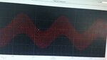
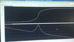
I use resistor feedback to generate variable voltage gain. the resistors are in the order of 10K. I found the output of VGA oscillates when used in closeloop. the envelope is the low frequency signal and it has high frequency part.
I have done ac sim and tran, the openloop gain and PM is O.K.
why does it oscillate?
and can anyone give me some advice to eliminate the oscillation?
Thank you all in advance!
 

The oscillation of VGA

Can you post the circuit and the bode-plot open-loop?

Right now I can only give you common problems that designers meet that lead to oscillation:
1) Forget to analyze both common-mode oscillation AND differential-mode oscillation
2) Realistic parasitics around Vcc and GND, as well as output are not included.
3) When doing loop analysis, do not properly open the loop to find gain/phase margin.
4) Look at just PM and GM, and do not look at the shape which may indicate problems elsewhere.
5) Do not consider all possible load impedances. Just because it's stable at your simulated load does not mean it will be stable at all loads.

Hope this helps for now. Again, if you post the circuit, frequency of oscillation and how you simulated phase/gain margin (and their plots) then we can provide you with a lot more feedback.

Greg
 

Re: The oscillation of VGA

Can you post the circuit and the bode-plot open-loop?

Right now I can only give you common problems that designers meet that lead to oscillation:
1) Forget to analyze both common-mode oscillation AND differential-mode oscillation
2) Realistic parasitics around Vcc and GND, as well as output are not included.
3) When doing loop analysis, do not properly open the loop to find gain/phase margin.
4) Look at just PM and GM, and do not look at the shape which may indicate problems elsewhere.
5) Do not consider all possible load impedances. Just because it's stable at your simulated load does not mean it will be stable at all loads.

Hope this helps for now. Again, if you post the circuit, frequency of oscillation and how you simulated phase/gain margin (and their plots) then we can provide you with a lot more feedback.

Greg

I have the same problem when I'm trying to design a pseuso-differential VGA. The CMRR simulation shows oscillation potential as shown in the following figure, in which the peak is at about 30dB. And the transient simulation with a common mode signal input gave some oscillation waves.
could anyone give me some hints to deal with this problem?
Thanks in advance,
abcyin
 

Attachments

  • DSC_0019.jpg
    DSC_0019.jpg
    2.2 MB · Views: 130
  • DSC_0020.jpg
    DSC_0020.jpg
    1.8 MB · Views: 117

Re: The oscillation of VGA

I have done ac sim and tran, the openloop gain and PM is O.K.
why does it oscillate?

How did you find the PM? What was the method applied?
 

My VGA is a pseudo-differential one, everything is fine when I was running a differential-mode simulation, but when I connect the differential inputs together, with a common mode source, to get the common-mode performance, such as common mode gain and the transient response, I can expect a poor common-mode rejection as its a pseudo-differential one, but a huge positive common mode gain is arised, and the transient simulation shows oscillation as shown in the above post.
And as for the PM performance, I use CMDM probe to simulate the CM and DM performance, the PM is alright for both.
If anyone is interested in the circuit, I could also post it here.

Thanks in advance.
 

And as for the PM performance, I use CMDM probe to simulate the CM and DM performance, the PM is alright for both.

My question was not if the PM is OK, but HOW it was determined!
Did you apply loop gain analysis?
 
  • Like
Reactions: abcyin

    abcyin

    Points: 2
    Helpful Answer Positive Rating
My question was not if the PM is OK, but HOW it was determined!
Did you apply loop gain analysis?

Sorry the PM is not OK anymore, I did the stability analysis again, and the bondwire model is included in the simulation file, the simulation results is shown in the following figure, the curve looks like there is a resonance frequency. while the curve is smooth when the bondwire is removed, PM OK then.
 

Attachments

  • DSC_0018.jpg
    DSC_0018.jpg
    1.5 MB · Views: 113

Status
Not open for further replies.

Part and Inventory Search

Welcome to EDABoard.com

Sponsor

Back
Top