Continue to Site

Welcome to EDAboard.com

Welcome to our site! EDAboard.com is an international Electronics Discussion Forum focused on EDA software, circuits, schematics, books, theory, papers, asic, pld, 8051, DSP, Network, RF, Analog Design, PCB, Service Manuals... and a whole lot more! To participate you need to register. Registration is free. Click here to register now.

How to drive stepper motor MOTS4/SP 2.5A 1.8° with PIC 16F Microcontroller

Status
Not open for further replies.

engr_joni_ee

Advanced Member level 3
Joined
Nov 3, 2018
Messages
750
Helped
2
Reputation
4
Reaction score
4
Trophy points
18
Activity points
6,231
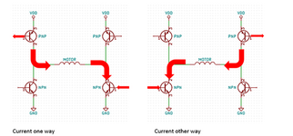
I have stepper motor MOTS4/SP 2.5A 1.8° which is also suitable for (3D printer): Velleman K8200 MOTS4/SP. This motor is rated for 3.1 V.


Is it possible to drive the this stepper motor with ULM2003 and PIC 16F Microcontroller at 5 V ? If the voltage limitation is absolute 3.1 V then how can I connect this stepper motor having 3.1 V rating with ULM2003 and PIC 16F Microcontroller which are operating at 5 V ?
 

Hi,

the 3.1V is the DC rating.
But if you want some good torque and some RPM you don´t drive a stepper with "constant voltage".
Constant voltage causes much heating when the motor stands still .. and cuases the torque reduced when rotating.
Only useful for cheap, low performance applications.

Thus one usually drives a stepper with constant current.
It causes limited heat when stand still but ensures good torque at some RPM.
Even if a stepper is designed for 3.1V DC it may be operated with 24V (pulses) or even more.

No wonder there are dedicated stepper driver ICs doing this stuff for you.
Most come with additional features like microstepping, current reduction on stand still, simple control interface (DIR, STEP, ENA).....but also high performance with complete control loops.

My recommendation: buy a cheap "true" stepper control module. Many different are available for hobbyists.

Klaus
 

I don't know ULM2003, are you talking about ULN2003? The driver isn't suited for 2.5A.

Also MOTS4 is a bipolar stepper motor (4 wires), it must be driven by bridge drivers.
 

Yes, I will drive this motor with h-bridge driver that can deliver 2.5 A current. The h-bridge transistors will be driven by PIC16F. I guess it should be fine to power up the h-bridge with 5 V and then 5 V pluses will be send to the stepper motor which is for some reason is rated for 3.1 V.
 

To achieve fast step rate, you would need to drive the motor with constant current and higher supply voltage. Applying fixed voltage of 3.1 V is a simple method to limit the motor current to about 2.5 A without a constant current controller. It's absolutely o.k. if you don't need higher speed or e.g. microstepping.
 

I am still wondering if I send 5 V pulses to the motor through the h bridge then how much constant current limit should I set in the h bridge. At the moment I just want to make it work with 5 V pulses, speed and torque are not very important in the beginning
 

Hi,

if torque and speed is no problem, then use as low current as possible.

Maybe 0.5A will do.
Test it.

Klaus
 

I am thinking to make the h-bridge driver using NPN BD 139 and PNP BD 140. I have attached the schematics. I will also add diodes to protect each BJP transistors.

I am wondering how to limit the current if I power the h-bridge by 5 V. I would like to limit the current around 500 mA. Each coil in the bipolar stepper motor has a resistance of 1.25 ohm. When the current flows through any of the coil, it has to run through two diagonal BJP transistors that has to turned on through Microcontroller.

In order to limit the current around 500 mA, do I need to add a resistor of around 10 ohm in series to each coil of the bipolar stepper motor ? I = V / R = 5 / 10 = 0.5 mA
 

Attachments

  • Schematics_4.png
    Schematics_4.png
    59.7 KB · Views: 80

Hi,

You are free to do what you want.
But for me it seems you go a hard way. And I see not much benefit in "learning"

Using your full bridge with additional base driver circuits
* needs a lot of base current (50mA @V_CE=0.5V and I_C=500mA) .. maybe more than your microcontroller can drive
* needs 13 parts (8xBJT, 8x diode, 2x Current_limiting_resistor, 8xBase resistor (at least ) )
* has more than 1V voltage drop
* has 4x 0.25W = 1W power disspation in the BJTs, (ignoring switching loss)
* has 4 x 50mA x 5V = 1W base drive power dissipation
* has 2x 1.7W = 3.4W in the current limiting resistors
* needs a control scheme which includes dead time.

A lot of effort, a lot of generated heat...

And I think the cost is higher than using cheap dedicated stepper motor driver modules.

***

Current limiting resistor calculation:
(for every resistance calculation you need to use
* the voltage across the device (not the total voltage as you did)
* the current through the device
)

Signal flow:
* 5V supply (total 5V)
* voltage drop in upper BJT (0.5V according datasheet at 500mA with I_B = 50mA)
* voltage drop in current limiting resistor (unknown for now)
* voltage drop in motor winding (0.5A * 3.1V / 2.5A = 0.62V)
* voltage drop in lower BJT (0.5V)
* GND

so the voltage drop in the current limitng resistor is:
5V - 0.5V - 0.62V - 0.5V = 3.38V
current = 0.5V
R = V / I = 3.38V / 0.5A = 6,76 Ohms

Klaus
 
Last edited:
If you use the old "hammer driver" ULNseries , you'd be lucky to get 3.1V out of the bridge. And with Arduino code, you'd be bit banging your head until it hurt. Get a CNC shield with proper FET drivers, GRBL code for Uno or better, and operate using your favourite GRBL encoded 3D printing software, or for speed tests on the system for slipping limits on acceleration , resonance, max print speed, or print or measure position overshoot errors vs speed and play with full step high speed, high torque, belt gear ratios vs fractional step high res/low noise low torque.

Get (free) GRBL Panel for windows and play with max a, max v , tweak current limit on CNC shield (amazing software), verify grounding on everything (RF shunt to earth ground to avoid USB errors and SMPS CM EMI) then save the results and transfer to your 3D CAD/CAM software

and oh by the way get bigger motors 12V and limit current for heat rise cooled by tiny muffin fans
 

Status
Not open for further replies.

Part and Inventory Search

Welcome to EDABoard.com

Sponsor

Back
Top