Continue to Site

Welcome to EDAboard.com

Welcome to our site! EDAboard.com is an international Electronics Discussion Forum focused on EDA software, circuits, schematics, books, theory, papers, asic, pld, 8051, DSP, Network, RF, Analog Design, PCB, Service Manuals... and a whole lot more! To participate you need to register. Registration is free. Click here to register now.

How to Detect Analog Audio Output Coming from Set Top Box or DTH

Status
Not open for further replies.

xpress_embedo

Advanced Member level 4
Joined
Jul 5, 2011
Messages
1,154
Helped
161
Reputation
396
Reaction score
189
Trophy points
1,353
Location
India
Activity points
10,591
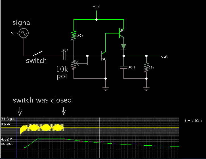
I have to detect the analog audio output from the set top box.
Means want to detect whether the audio is coming from channel or not.

How can i detect mute condition, is there any method do so.
 

If you can assume that there is audio signal above some amplitude whenever it's not muted, then you can do it fairly easily, with an envelope detector and a comparator, depending on what you need as your output.

An envelope detector can be as simple as a series diode followed by a parallel RC to ground. You adjust the R and C for the desired frequency range and response speed. If the signal can be low-level, compared to a diode's forward voltage, then you could use an active "ideal rectifier" circuit instead of a diode, usually made with an opamp, so that it will rectify down to about zero volts.

Basically, the envelope detector will have output of about zero volts when there is no audio, and output above zero whenever there is audio. You might want to adjust the R and C to make it "slow", so it will hold up the voltage when there are short gaps in the audio. But note that any long gap with no audio signal will look like muting is on. I don't see any way around that, if the audio output is all you have access to.

It would be a good idea to simulate it in LT-Spice, or something like that, so you can adjust the R and C easily, and so you can figure out how to get the output level you need. LT-Spice can use WAV files of actual audio as inputs (and outputs), which might be handy for testing in this case.
 
Here is a simulation.

The transistors amplify an incoming audio signal, and apply it to a peak detector. The capacitor quickly charges.

When the signal ends, the output capacitor starts to lose its charge.

 
Here is another circuit that will do what you need.
Also attached is the LT-Spice ".asc" schematic file.
To run the simulation, remove the ".txt" from the filename,
and run with LT-Spice, which is a free download from https://www.linear.com .
I also attached a plot of the output for very low-amplitude audio inputs, so you can see the behavior with the current component values.
Everything can be varied, by changing component values. You could also use things like a comparator and/or logic inverter, after the output, to do thresholding or changing the logic level or polarity.
 

Attachments

  • MUTE-OFF_DETECTOR.jpg
    MUTE-OFF_DETECTOR.jpg
    210.7 KB · Views: 123
  • Mute_detector.asc.txt
    5.1 KB · Views: 62
  • MUTE-OFF_DETECTOR_.01-.011.jpg
    MUTE-OFF_DETECTOR_.01-.011.jpg
    293 KB · Views: 79
Last edited:
Status
Not open for further replies.

Similar threads

Part and Inventory Search

Welcome to EDABoard.com

Sponsor

Back
Top