Continue to Site

Welcome to EDAboard.com

Welcome to our site! EDAboard.com is an international Electronics Discussion Forum focused on EDA software, circuits, schematics, books, theory, papers, asic, pld, 8051, DSP, Network, RF, Analog Design, PCB, Service Manuals... and a whole lot more! To participate you need to register. Registration is free. Click here to register now.

How to design the the following operation

Status
Not open for further replies.

EHY

Member level 1
Joined
Apr 2, 2015
Messages
36
Helped
0
Reputation
0
Reaction score
0
Trophy points
6
Activity points
235
sr.jpg


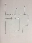
As i attach the image, I want to design the circuit like SR-latch but quite different.


If the rising edge of S signal is high, output Q is high(set)

Otherwise, if the rising edge of R signal is high, output Q is low(reset).


output Q of conventional SR-latch using nor gates is low when S and R is high (S=1,R=1)

I don't want this operation.

I just want circuit. the rising edge of S and R controls output signal Q.

plz help me`~:cry:
 

Hi,

Instead of using fli flops you could use combinatorial solution:

Q = C AND !R

Two resistors and a bjt is sufficient

Klaus
 

Hi,

Instead of using fli flops you could use combinatorial solution:

Q = C AND !R

Two resistors and a bjt is sufficient

Klaus

Thank you but, What is solution using Flip Fliops?
 

How to design the following operation??

I want to design circuit

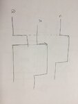
when the rising edge of signal S is triggered, then output Q is high(set)

and when the rising edge of Signal R is triggred, then output Q is low(reset)

(edge triggered SR-flip flop ?!)


I don't want combinational logic , Q=S and ~R

plz help me~
 

Re: How to design the following operation??

The edge triggered Flip Flop may be designed using gates is also called a Type II Phase Detector.

Either it is level sensitive or edge sensitive.

It is impossible to do without Logic. What are your real constraints?
 

Re: How to design the following operation??

The edge triggered Flip Flop may be designed using gates is also called a Type II Phase Detector.

Either it is level sensitive or edge sensitive.

It is impossible to do without Logic. What are your real constraints?

i want operation of the attached image
image.jpg
 

Re: How to design the following operation??

Hi,

i can´t imagine a dual clock triggered flipflop.

What´s wrong with the combinatorial solution? Is it too easy?


Klaus
 

Re: How to design the following operation??

Hi,

i can´t imagine a dual clock triggered flipflop.

What´s wrong with the combinatorial solution? Is it too easy?


Klaus

because simple cmos gate logic has process speed limitation
so i have to implement such CML type circuit

- - - Updated - - -

What about if R precedes S?

If rising edge of R signal is trigerred firstly, the output Q is just low
and then if rising edge of signal S is trigerred , the output Q is high
 

Status
Not open for further replies.

Similar threads

Part and Inventory Search

Welcome to EDABoard.com

Sponsor

Back
Top