electronic_satya
Member level 2
Hi all,
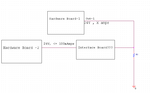
I will briefly explain my setup and shown as an attachment
1. The hardware board 1 on its output pin gives 24V and depending on the resistance value it gives out X amps current.
2. I have another hardware board-2 which is capable of reading up to 24V but the current capability is limited to some 100mAmps.
3. Now my requirement is to interface the hardware board -1 and hardware board -2 through some interface board so that only 24v appears on the input of Hardware board -1 and very little current comes in.
could somebody suggest me the design of the interface board i hope some opamp circuit will work?
Thanks in advance,
Regards,
satya