Bindu boora
Junior Member level 1
How to design control loop for duty cycle.I have gone through few papers .There was a gain Gvd which is transfer function Vout/duty cycle.How to derive this gain value?My circuit consists of AC supply of 110 to 120 V 400hz given to a transformer which give 5V and 4 mosfets connected to LCL filter? I need to regulate output voltage to 5V and output ac ripple should be 5mV and load regulation is 0.05%.Im not understanding how to design control loop.Can I get a clear steps to do it.I have gone through few papers containg error amplifier connected to lead lag compensator then to comparator for PWM to a mosfet drive and the connected to mosfet.How to design the compensator?I needs bode plot but I need Gvd value and everywhere I can find the gain value for LC filter but my filter is LCL.
Please help me
Please help me
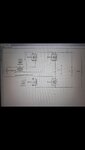
Attachments
Last edited: