saif haider
Full Member level 1
i need to design a phase generator that could gave a phase shift of 90degree lead or lag any suggestions
Follow along with the video below to see how to install our site as a web app on your home screen.
Note: This feature may not be available in some browsers.
thanks for ur suggestion but already gone through but their is no use plz help me i really need to make it for my final year projectHumungus said:I do not remember the structure by heart, but there are some all-pass filters that allows you to change the phase of the output signal by changing the value of just one component. Make a search on them.

could this circuit also be able to gave phase lag of 90 i mean -90degreeon1aag said:Hi Saif Haider,
If you want to design a 90 degrees phase shift oscillator you gonna
need a circuit that can do that, an integrator ( or a differentiator)
will perform that task. But you also have to shift the phase even
further in order to get your signal back to 0 or 180 degrees.
So you need two of those and an inverting amplifier to get the ac
signal back to 0 or a multiple of 360 degrees. The trick is to get the
ac phase shift to 0 degrees and the dc "phase shift" to 180 degrees to
keep the circuit stable for dc.
Here's an example from the 1974 Nonlinear Circuits Handbook from
Analog Devices.
You can build this circuit with modern fet input opamps like the TL084.
Forget both four quadrant multipliers, they are only needed if you want
the frequency to be controllable by a dc voltage, they only act as voltage
controlled amplifiers. Both 1N935's are temperature compensated 9 volts
zenerdiodes but they should be connected in series, not in parallel.
If you want the frequency to be variable, replace both 10k resistors of
the integrators by a 1k resistor in series with a 10K (stereo)potentiometer
and you could switch the 15 nF capacitors to get different ranges.
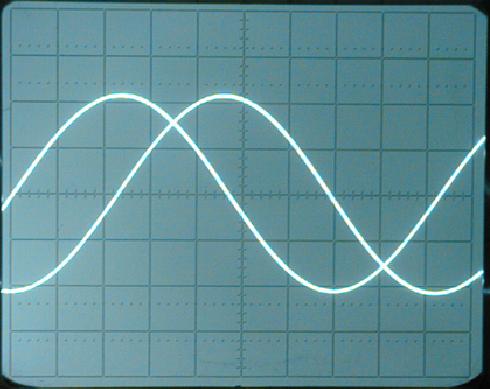
My simulator says it's OK.
Vert. 5V/div Hor. 100µS/div
on1aag.
i know that phase shift means that you gave a lead or lag to current with refference to time with voltage but the general question is how this is possible, how to perform -90degree lag i know we us sin to cosine converter but how it perform in case of -90degreeon1aag said:Hi Saif Haider,
Phase doesn't mean anything if it isn't referred to something else.
If there's a phase lag or lead will depend on what you assume to be
the reference.
on1aag.
saif haider said:could this circuit also be able to gave phase lag of 90 i mean -90degreeon1aag said:Hi Saif Haider,
on1aag.
xxargs said:saif haider said:could this circuit also be able to gave phase lag of 90 i mean -90degreeon1aag said:Hi Saif Haider,
on1aag.
use 180 degree unit-amplifier (inverter) on 90 degree output and you make -90 degree output.
saif haider said:xxargs said:saif haider said:could this circuit also be able to gave phase lag of 90 i mean -90degreeon1aag said:Hi Saif Haider,
on1aag.
use 180 degree unit-amplifier (inverter) on 90 degree output and you make -90 degree output.
i want to know that either this circuit works on 418MHz or not if not then tell what shall be the best design for desired freq
with best regards
xxargs said:saif haider said:xxargs said:saif haider said:could this circuit also be able to gave phase lag of 90 i mean -90degreeon1aag said:Hi Saif Haider,
on1aag.
use 180 degree unit-amplifier (inverter) on 90 degree output and you make -90 degree output.
i want to know that either this circuit works on 418MHz or not if not then tell what shall be the best design for desired freq
with best regards
You not talk about high frequency before, is hard to find OP-amp working well in this frequecy range and frequency depend componet going to very small value.
For rigth answer, you must give right information on your problem - and frequency range is very importent info to make right answer ie. totaly different solution if we talk low (< 1 MHz ) or high frequency (> 10 MHz)... if no frequency information given - answer is near always related to low frequency solution.
---
Other way in high frequency range is using single oscillator and split output to two way with 90-degree hybrid[1] and/or using different path length of transmissions line. For 418 MHz need only 179.4 mm (air way length) or around 122 mm RG223-cable different path-length to make 90 degree differense between output.
[1] see Anaren or Mini-circurit for 90-degree splitters/hybrids, you can also make splitters, coupler structures and delay-strip on PCB via microstrip etc.
on1aag said:Hi Saif Haider,
Phase doesn't mean anything if it isn't referred to something else.
If there's a phase lag or lead will depend on what you assume to be
the reference.
on1aag.
hi plz do consider this it importanton1aag said:Hi Saif Haider,
If you want to design a 90 degrees phase shift oscillator you gonna
need a circuit that can do that, an integrator ( or a differentiator)
will perform that task. But you also have to shift the phase even
further in order to get your signal back to 0 or 180 degrees.
So you need two of those and an inverting amplifier to get the ac
signal back to 0 or a multiple of 360 degrees. The trick is to get the
ac phase shift to 0 degrees and the dc "phase shift" to 180 degrees to
keep the circuit stable for dc.
Here's an example from the 1974 Nonlinear Circuits Handbook from
Analog Devices.
You can build this circuit with modern fet input opamps like the TL084.
Forget both four quadrant multipliers, they are only needed if you want
the frequency to be controllable by a dc voltage, they only act as voltage
controlled amplifiers. Both 1N935's are temperature compensated 9 volts
zenerdiodes but they should be connected in series, not in parallel.
If you want the frequency to be variable, replace both 10k resistors of
the integrators by a 1k resistor in series with a 10K (stereo)potentiometer
and you could switch the 15 nF capacitors to get different ranges.
My simulator says it's OK.
Vert. 5V/div Hor. 100µS/div
on1aag.
let me know either it will work on 418mhz freqbigpop said:use DLL which can generate any phase shift you wanted