Continue to Site

Welcome to EDAboard.com

Welcome to our site! EDAboard.com is an international Electronics Discussion Forum focused on EDA software, circuits, schematics, books, theory, papers, asic, pld, 8051, DSP, Network, RF, Analog Design, PCB, Service Manuals... and a whole lot more! To participate you need to register. Registration is free. Click here to register now.

How to deembed the effects of the waveguide on a waveguide-to-coax transition?

Status
Not open for further replies.

mmrobles

Junior Member level 2
Joined
Jul 28, 2010
Messages
20
Helped
2
Reputation
4
Reaction score
2
Trophy points
1,283
Activity points
1,439
I'm investigating the S-parameters of a waveguide-to-coax transition and I want to know how to remove (deembed?) the effects of the waveguide itself to the transition. How to do it? After doing the normal simulation of the transition with waveguide (thru CST), should I make a second simulation using a waveguide structure only then subtract it (S-param in dB) on the S-parameters of the original structure? I'd appreciate any reply. Thanks!
 

I've never used CST. But, in HFSS, I would just de-embed the effect of the waveguide by moving the reference plane of the waveguide port a certain distance into the waveguide itself. If you want to deembed the waveguide completely, then move the reference plane right up to the waveguide discontinuity.

You cannot simulate them separately, and subtract S-parameters because the effect of the discontinuity would not be modeled, and this important for accurate simulation of the transition.

I'm sure this can all be done equivalently in CST.

Hope this answers your question.
 

Oh, I've tried to do that on CST, but the changes only affects the phase of the S-parameters. Shouldn't it affect the magnitude as well? Or is deembedding only essential for getting the true phase values? Thanks for the help!
 

De-embedding does change the phase response due to shift of the reference plane. Since the waveguide itself exhibits very low losses, you will not see a significant change in the magnitude response.

However, generally speaking, the de-embedding process affects both magnitude and phase. Many software packages (like Sonnet) recommend that the structure that is to be de-embedded be simulated in a lossless fashion for maximum accuracy, so that the deembedding processes essentially deals with phase changes. In principle, this should apply to any simulation software.
 

Many software packages (like Sonnet) recommend that the structure that is to be de-embedded be simulated in a lossless fashion for maximum accuracy

For Sonnet, de-embedding also works for lossy lines.

---------- Post added at 17:35 ---------- Previous post was at 17:29 ----------

Oh, I've tried to do that on CST, but the changes only affects the phase of the S-parameters. Shouldn't it affect the magnitude as well? Or is deembedding only essential for getting the true phase values?

It depends on the losses of your waveguide, and on the reference impedance for the S-parameters.
Some results refer not to a fixed reference impedance, but to the impedance of the feedline itself. In this case, the feedline itself is perfectly matched by definition.
 

For Sonnet, de-embedding also works for lossy lines.

Hi Volker,

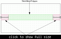
In the known bugs section on the sonnet website, there is an entry which says "Ports Attached to Thick Metal May Produce Inaccurate Response Data" (KB-ref: TT5552) and cites the cause as:

"When the de-embedding is done on the circuit, the calibration standards do not include the vias which are required to model the thick metal. This may produce inaccurate response data and is more likely to occur as the calibration lengths or reference planes increase in length."

Sonnet suggests the work around shown below.


Is this issue corrected in the newer releases of Sonnet?

Thanks for your input.
 

It depends on the losses of your waveguide, and on the reference impedance for the S-parameters.
Some results refer not to a fixed reference impedance, but to the impedance of the feedline itself. In this case, the feedline itself is perfectly matched by definition.

Oh, I see. Well, actually my waveguide-to-coax transition uses an Aluminum material (which is a lossy metal) as its shell, that's why my professor told me to de-embed the waveguide from the transition, but did not told me how. Now CST only provides a de-embed function only for the phase value, which means it does not consider the lossy property of my structure. So my question now is how do I properly de-embed the waveguide structure apart from the transition to see the effects of the lossy structure? What should I subtract from what to get the proper S-paramters, and how? Thanks a lot for your replies.
 

Status
Not open for further replies.

Part and Inventory Search

Welcome to EDABoard.com

Sponsor

Back
Top