Continue to Site

Welcome to EDAboard.com

Welcome to our site! EDAboard.com is an international Electronics Discussion Forum focused on EDA software, circuits, schematics, books, theory, papers, asic, pld, 8051, DSP, Network, RF, Analog Design, PCB, Service Manuals... and a whole lot more! To participate you need to register. Registration is free. Click here to register now.

How to debug this sound COB circuit?

Status
Not open for further replies.

alaasalama

Newbie
Joined
Apr 1, 2021
Messages
4
Helped
0
Reputation
0
Reaction score
0
Trophy points
1
Activity points
35
Hi guys!
So, my kid has this "Animals Sounds Book" which is broken and doesn't produce any sound now, although the batteries are good.

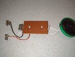
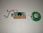
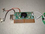
I've attached two images showing the COB circuit, but I'm beginner and I don't know how to trigger these metal strips to test the output?

Also, any general idea about how to debug this board would be appreciated, wiring diagrams or what to search for?
 

Attachments

  • circuit2.png
    circuit2.png
    788.1 KB · Views: 106
  • circuit.png
    circuit.png
    816.3 KB · Views: 107

* Do you measure battery voltage at the red & black wires? Across copper traces which carry same voltage?

* The upper speaker wire looks like it was re-soldered. Can you locate tiny thin wires at each solder joint, which go to the speaker coil? These must be unbroken and properly soldered.
 

Yes, I measured that, it was 5 volts at these red/black wires, and I got the same readings through some of these metal strips (b0, b1, a0, a1, etc...)

I'll check the speaker trick though! thanks!
 

Just an update here, perhaps you have any idea?


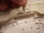
Also, I've attached some extra images and I feel I need to mention the book was working fine, then some buttons were working and others not, then the voice was cracking, not clear, then no sound at all.
 

Attachments

  • book_4.jpeg
    book_4.jpeg
    98.8 KB · Views: 112
  • book_3.jpeg
    book_3.jpeg
    126.6 KB · Views: 101
  • book_2.jpeg
    book_2.jpeg
    122.9 KB · Views: 106
  • book_1.jpeg
    book_1.jpeg
    62.7 KB · Views: 106

Can we get a photo of the front side of the sound book?
Do you have any LED on the sound book? Outer contacts (V+ and #) could be for it - rough guess.
Other 6 contacts could be a matrix "keyboard" so measuring continuity will give you no relevant data.
Also, is your speaker ok? (Desolder one wire from PCB and measure resistance).
 

An easy way to check the speaker is to test its resistance. It should make a clicking sound and indicate 8 ohms as it's labeled. It's safer to disconnect it first (per post # 5 because the ohmmeter range sends current through the leads and it might be unhealthy for the pcb).

then some buttons were working and others not, then the voice was cracking, not clear, then no sound at all.

Describes gradual failure rather than sudden. If not the batteries declining then probably failing circuitry in the IC.

Can you trace the wiring of the buttons? I guess the different copper contacts get a signal from each button?

Can you determine what pressing a button does? Does it connect to positive voltage or to ground?
You should make sure before you do the straightforward test, namely to energize each copper contact in turn and listen for sound. The ribbon cable no doubt carries tiny current, so you should include a resistor in the loop with your meter on low ammeter range. A reasonable value is 10 Kohm.
 

I took out the speaker and measured its resistance, and it was 20 Ohms, not 8 as labeled, does that mean it's broken? I've tested another "working speaker" from another toy, and it gave the same (although this one doesn't have a label, so I'm not sure).

That's a better video showing the whole book and how it works:

Thank you for all the information you are writing here, I'm enjoying my time learning new stuff because of you, I appreciate that!
--- Updated ---

Just an update: I'm now sure the speaker is working fine because I tested it on another toy and it worked.

I've one question though, should be there a voltage difference between the speaker terminals while connected to the board? Because now there's not.
 
Last edited:

It's probably okay for the speaker to be 20 ohms even though it's labeled 8 ohms.

Only when it's sounding should voltage appear across its terminals. It should be AC only. If there's any DC component then the audio amplifier is not the most efficient design, even though the speaker is not necessarily harmed by low DC current levels.

It drains the battery for the speaker to read any voltage when idle.
 

Status
Not open for further replies.

Similar threads

Part and Inventory Search

Welcome to EDABoard.com

Sponsor

Back
Top