Continue to Site

Welcome to EDAboard.com

Welcome to our site! EDAboard.com is an international Electronics Discussion Forum focused on EDA software, circuits, schematics, books, theory, papers, asic, pld, 8051, DSP, Network, RF, Analog Design, PCB, Service Manuals... and a whole lot more! To participate you need to register. Registration is free. Click here to register now.

How to de-couple feed cable for measurements of electrically small wide band antenna?

Status
Not open for further replies.

AndreyG

Full Member level 4
Full Member level 4
Joined
May 10, 2010
Messages
196
Helped
27
Reputation
54
Reaction score
27
Trophy points
1,308
Location
Vancouver, Canada
Visit site
Activity points
2,946
How to de-couple feed cable for measurements of electrically small wide band antenna?

I normally use bazooka-type coaxial balun to decouple feed cable. In this project bandwidth is large (0.85 - 2.1 GHz) and bazooka balun does not have the required bandwidth to cover the band. Plus antenna assembly is pretty small, significantly less then the choke will be at low frequencies.

I thought to use ferrite beads but they absorb energy, I see it with NA.

Did anybody encountered this problem?

Thank you
 

This is a common problem in real measurements. You can be happy that nowadays ferrite is available that performs well in the GHz range. All these materials have relative low permeability (NiZn materials).

the approach is two step: leaving the structure where the common mode voltage is the lowest and use very thin cable with thight fitting ferrite cores around the cable. the goal is to get a very high common mode impedance so that the remaining common mode current does not interfere with the radiation pattern.

Route the cable to the point of lowest voltage on the antenna structure (mostly a ground plane, or current maximum), so that the common voltage on the cable is as low as possible. Then let the cable leave the antenna. You may simulate the antenna to find a current maximum on the ground plane or other structure.

Use a small size cable (diameter).

To raise the common mode impedance of the cable, you may use low permeability ferrite cores that have a tight fit around the cable. Thin cable enables you to use small ferrites with relative large Douter/Dinner ratio (as that matters).

if you have a very low permeability material that performs well on 2 GHz, but not at 0.8 GHz. you may use that ferrite core together with a core with somewhat higher permeability, so that you get a high common mode impedance over your full frequency range. The ferrite with the best perfomance at the highest frequency range is closest to the antenna.

Using many small cores further increases the common mode impedance.
 
and you do not want to use a tiny smt balun from someone like minicircuits for what reason?

another method might be to make a tiny vco, attach it to the antenna, sweep the frequency, and record the transmitted power with a calibrated receive antenna
 
Thank you for your replies gentlemen.

It is clear that currents will be induced on a cable in proximity to an antenna even it is electrically entirely unrelated to antenna circuit - this is the nature of electromagnetic waves. Covering section of coax with ferrites reduces induced currents effectively yet ferrites absorb electrical energy. I see it if I place ferrites close to radiating antenna radiation level drops.

The idea of making battery powered oscillator conceptually is awesome however it's size will be close to size of my antenna, I need it to be tunable within 0.85 - 2 GHz and - the main drawback - I can not measure impedance of my antenna this way. Using Network Analyzer for antenna work is very convenient.

>> ... use a tiny smt balun ...
this would be my preferred solution. However I still struggle to understand if such device indeed decouple my coaxial cable. Especially the ones rated to 2 GHz - called Guanella Baluns.
In Ham literature they are called Current baluns and recommended for decoupling cables at lower frequencies. However I struggle to understand why would they stop the currents from running back over coaxial shield.
Any insights if this is the device that would decouple the feed cable?
 

I design and measure wide band antennas in the range 700-2700 MHz. For anechoic chamber measurement, how to route measurement cable in a good way, not interfering the radiation measurement, is seldom a big problem and more or less do it exist a branch standard rules how it should be performed.
Cellphone manufacturer do often require its subcontractors that measurement should be done in a way that they then can verify result in their own anechoic chamber.
Ferrite filled coaxial-cable in measurement area, ~300 mm, routing cable perpendicular to PCB and normally in the middle of PCB if antenna is placed at short end of PCB. PCB/ground length is typical 50-150 mm. Never let the cable leave PCB in opposite end of antenna location.
Depending on situation can different types of ferrite material be required. Also sleeve balun is used sometimes. They are narrow band but as most measurements are performed narrow-band, one frequency band per measurement, even for wide band antenna, is it no problem.
Here can you find some of the equipment I use: https://www.antune.net/calibration.html

Worst problem so far have been with a headset add-on receiver. narrow band 863 MHz. As main board was 7 by 7 mm in size was it very complicated to measure antenna radiation pattern without affecting result with measurement cable.
At a such long wavelength in combination with short a mainboard PCB was correct routing of the cable very critical. The routing had to start with a ferrite covered cable very close to the antenna and finding a neutral angel to leave PCB. Cable was directly routed thru a SAM.
1DT20.jpg
The part besides the hearing aid is the receiver. The three-pin connection is a standard. In the hearing-aid are all these three pins isolated with both coils and ferrite as standard. That is bad from antenna view as it else had extended the small ground-plane.
Final product which includes receiver and antenna was housed in a volume of 7*7*7 mm.
 
Last edited:
Great thank you for your commentaries it is very useful to me. I wish to hear more. At the same time let me share concerns regarding using ferrites to decouple feed cable.
We are all aware that ferrite absorbs EM energy. It is not always clear how effectively ferrites do it. To demonstrate I conduct simple experiment you can easily repeat.
1. I construct a dipole. I tune it to 2.48 GHz. I add coaxial feed cable with no choke or any other means to de-couple it. I add feed cable accurately in the middle of the dipole and orthogonally to dipole’s electrodes. This way my coaxial cable carries very little current, it does not need to be decoupled. I demonstrate this by measuring patterns of my dipole: my co-polarized pattern shows perfectly balanced undisturbed donut shape; my orthogonally polarized measurement shows levels 25 – 30 dB below co-polarized measurement. These are my proves that very little current runs on the outside of my coaxial feed cable.
2. Now I can add coaxial choke if I want. I can tune the choke to required resonant frequency by observing that the resonance of my dipole does not shift. I can re-do radiation plots and show that radiation levels remain exactly the same. My choke does not do any useful work in this configuration but it does not offset resonant frequency of the structure neither it absorbs any energy.
3. Now I install ferrite choke instead. I use standard ferrite of the type that clamps on cables. Package size 32x22x22 mm, called NF-100. Two things happen:
I lose lots of power. I see it in pattern measurement or from simple boresight point measurement. When my ferrite choke installed ~4 mm away from the dipole electrodes I lose 2.5 dB on the boresight.
The resonant frequency as I see it on S11 plot goes up. In configuration described above S11 dip shifted from 2.48 GHz to 2.58 GHz.

I conclude that ferrite choke on feed cable skews antenna characterisation results.
Am I wrong in my experiments or reasoning? If I am please advise where.

If not I would be very hesitant using ferrites to decouple feed cables. I am aware that using ferrite chokes is method recommended by cellular carrier acceptance bodies but this does not mean the results are correct. Moreover such practices put antenna developer in disadvantage: ferrites on our cables rob us from radiating power we trying to retain.

Hence the question: are there any other convenient ways to de-couple feed cable in broadband measurements? Tomorrow I will try balun transformer see how that works.
 

Do find it confusing if a unbalanced dipole at resonance frequency (no img. part) shows up as as balanced. That is for several reasons, but a simple dipole construction will most likely show up as something 60-70 Ohm=> It will cause reflections. It is possible to tune it for a lower impedance by for example increasing wire thickness but if that tuning is done in an unbalanced setup, is that exactly what you get.
It is then not possible to add any balun afterwards as that will detune the antenna due to that measurement cable is a part of the antenna.:!:

Big ferrite-clamps is not the right tool for a small 2.4 GHz antenna. NF-100 is however relative less useful at these frequencies. Peak absorption around 300-500 MHz. Select another ferrite material and it will affect the antenna even worse. :lol:
Check the link above where I show my measurement cables. It is the thin coaxial cables filled with 20-30 small ferrite tubes that have a more reasonable size. They will not affect your measurement even if used all the way up to the antenna feeding point.
My smallest ferrite tubes have a diameter of less then 2 mm. Do use different tube material depending on frequency range.
I also use ferrite clamps of the size you is using, have plenty of them around the semi-rigid fixed measurement cables and thicker coaxial-cables connected to instruments, mostly just in case, but the cable to which I connect DUT at turntable have a lot of them due to that I not want it to be visible as a secondary radiator in the chamber.
It is however hard to get hold on ferrite clamps that is effective at 2+ GHz. If data sheet only cover up to 500 MHz, select something else as clamp for 2 GHz.
If space allows it, is often advantage to use several ferrites and sometimes also mix different materials. A ferrite is not an absolute block for unbalanced current, it is just a serial resistor that successive absorbs these currents.

but this does not mean the results are correct.
:shock:This is a bit basic knowledge if you are in this business. It is simple to verify just by measuring resulting polarization pattern for different setups, just as you did.
But if I had got your result, had I spent a day on checking chamber calibration with known antenna references.
It exist exceptions from these general rules, such as when ground not really behaves as ground or that ground have an unlucky size. As that also result in an ineffective antenna is it probably not an antenna design the customer want to have anyway, so that is more or less hypothetical cases.
It exist a lot of reports that have investigated this matter in smallest detail. A good start can be Espoo University website and search for publications around "measurement of small antennas".
 
Regarding absorption of ferrites.

If you have a half wave resonating dipole with an impedance of around 50 Ohms, the voltage divides equally. So you can split the 50 Ohms into 2, 25 Ohms resistors in series with each dipole element. The common mode voltage as seen by the braid is half the input voltage.

One element is connected to the braid of the cable. When you add a ferrite that shows 500 + j0 Ohms impedance, there is some absorption, but this is in the 3% range (< 0.2 dB).

If you have a small structure and significant common mode current is present at the feed line, this may be the main contributor to the radiated power. So it isn't strange that after adding the ferrites the radiation is less and the antenna's input impedance is completely different (after adding the ferrites).

If your application allows, you may post a picture.

Another problem with (small) structures can be that the input impedance is relatively low, but the common mode voltage component is high. This happens for example in half wave resonating structures, but the feed is not in the middle (for example an off-center fed half wave dipole, or non-balanced small loop antenna). The common mode voltage can be significantly higher then the actual feed voltage. In my opinion, measurement in such cases approaches impossible.

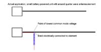
Example given below:


Here the highest voltage is on the battery powered unit. The position where the cable leaves the structure was first determined based on EM simulation. The antenna was extended to get additional inductance. Using the PCB ground of the actual unit as ground for the coaxial feed gave bad results. Ferrite selection was done based on material and measurement with VNA.
 
I thought to use ferrite beads but they absorb energy, I see it with NA.

I completely agree with the explanation WimRFP has given in this regard, although you probably may not like it. My criterion for an effective cable isolation is that moving the ferrite beads by a small amount doesn't change S11 any more.

The other question that should be considered is if measuring the isolated antenna on it's own corresponds to the actual application situation. I presume there will be a transmitter or transceiver of finite size that becomes part of the antenna in real live. So it's more realistic to measure the antenna with the transmiter board or a substitute.
 
Lots to learn here, thank you for your comments. please advice which ferrites to use in 1 - 2 GHz range and where to get them. I do not see anything resonant that high in Digi-Key catalog. What type of ferrite material this would be (in common cases ferrite material coded as two digits: like 43, 61 type). If you give me part numbers that fit on RG405 smi-rigid coax and where to buy them it would be the best.
How to empirically determine place on radiating structure to exit the cable?
 

I do not see anything resonant that high in Digi-Key catalog.
A quick google search: **broken link removed**
TOKO, TDK, Fair-Rite or Lairdtech do all have a a good assortment of different kinds of ferrite material.
A development kit from Fair-Rite is a good start as they also have reasonable good data sheets.
Many ferrite materials that peaks at 1 GHz are still acceptable at 2 GHz. Especially if cable routing allows use of several ferrites before measurement cable start act as an extension of existing groundplane. It is up to you and your customer requirement what is accepted as "good enough".
How to empirically determine place on radiating structure to exit the cable?
Connect a cable anywhere along PCB, except at opposite end of where antenna is placed, as that always is a more or less hot area. Measure S11 and check where a finger can touch PCB and have minimal effect on measured impedance. That is a good point to place your measurement cable.
That "best place" can be frequency depending!

WimRFP example, when mainboard length only is a fraction of a wavelength is complicate for anyone to measure at. I agree with his discussion.
 
if you have a balanced antenna, like a dipole or loop, then something like this is to be used.

https://www.minicircuits.com/pdfs/NCS1-222-75+.pdf

there will be no direct currents on the coax shield because...there is no connection between the coax shield and the antenna. The coax shield is at zero volts, while the two terminals of the antenna are driven + and in voltage in a balance way. the coax shield will just act like any other metal piece "in the area".
 
Today I experimented with higher frequency ferrites. I used part Laird HFB075024-000 - the highest frequency ferrite available from Digi-Key. They are not particularly high frequency - resonant at some 800 MHz. Fair Rite offers parts with resonance above 1 GHz but it will take time to get it. I placed string of ferrites on feed cable of my dipole.
This type of ferrites do not result in visible losses just as you said. I observed the action of these ferrites manifested in reduced cross-polar radiation of the dipole. With the ferrites I used it tapers off at some 1.6 GHz. Pretty good.
I also tried transformer (part CX2156 by Pulse). Using transformer results in insertion loss which is frequency dependent. Transformer results in better choking action at high frequency (it is rated to 2.7 GHz). With transformer I could not make the dipole's impedance to look exactly the same as without. I calibrated NA at the output of the transformer and still it was different. Also with transformer feed structure becomes more difficult to make.
My overall conclusion: ferrites is a way to go. I just need to find real high frequency ones.
I want to thank everybody who contributed to this discussion. I learned something new in last two days.
 

Status
Not open for further replies.

Part and Inventory Search

Welcome to EDABoard.com

Sponsor

Back
Top