Continue to Site

Welcome to EDAboard.com

Welcome to our site! EDAboard.com is an international Electronics Discussion Forum focused on EDA software, circuits, schematics, books, theory, papers, asic, pld, 8051, DSP, Network, RF, Analog Design, PCB, Service Manuals... and a whole lot more! To participate you need to register. Registration is free. Click here to register now.

How to create impedance model in Cadence Spice?

Status
Not open for further replies.

volkantr

Junior Member level 2
Joined
Dec 23, 2007
Messages
20
Helped
0
Reputation
0
Reaction score
0
Trophy points
1,281
Activity points
1,439
Hi everyone,

In a project I designed a class AB type power amplifier to drive a load that's characteristics are changing according to frequency.

the load is acoustic transducer (a piezo material).
I have a look up table that shows at what frequency, what characteristics the load have. And I could make the simulations for the system for only one frequency by placing r-l-c components for the transducer, but in the system frequency is continously changing. I want to create a load that I can enter all the information(at what frequency,what impedance) from an excel table (for example). And by using this load in the simulation, I may be able to get results for whole frequency band.

Can I make this in cadence spice? (If yes! how can I do that? If not, how can I do that?)

I wish,I'm clear:)

thanks for replying
 

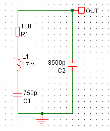
I don't use Cadence but the Spice I do use doesn't have the facility for a table for frequency dependant characteristics, as far as I am aware. The way I have simulated piezos is to create a simple model then adjust the values to try to match the measured characteristics. You may not get it perfectly right, but I tend to concentrate on getting the series resistance right, the separation of the series & parallel resonant peaks and the parallel capacitance. Then you end up with something like this:

9_1287064525.gif


I have done some with harmonic resonances as well - you just add more tuned circuits in parallel.
 

thanks for reply,
I used this way even get a reslt that gives idea about the design's performance but because of the critical point about the design
I need to make the design with the exact data.
 

Hi,
I have admittance vs frequency data in my hand li below, here I attached a xlsx file if you give me a procedure or a technique I'll be grateful
thanks
regards
 

Attachments

  • A-kısa.rar
    9.1 KB · Views: 102

Could you re-post the attachment - filzip & Rarzilla both cannot read it - corrupted.

Keith.
 

I hope this time it's OK.
 

Attachments

  • A-kısa.zip
    10.4 KB · Views: 116

Sorry, but I cannot open that either. I don't know why - I use zip & rar quite a lot without any problems.

Keith.
 

I attached data table in notepad and 2 graphics that show absolute value and argument of impedance. may be you can use this stuff to give some idea. If not thanks for everything in advance.
eyw
Volkan
 

Attachments

  • data.txt
    778 bytes · Views: 68
  • abs of impedance.bmp
    318.1 KB · Views: 100
  • argument of impedance.bmp
    296 KB · Views: 108

That looks tricky - it seems to be all over the place with no obvious devices making up the characteristics. You may be able to do it with a B arbitrary source. It also accepts max/min so you may be able to do it with multiple B sources to form a piecewise linear approximation. Sorry, it is not a method I have used so I cannot offer any help, but it is worth investigating I think.

Keith.
 

actually I tried to model this data with G device in LTspice, I create the model and it worked in frequency domain flawlessly. but in transient analysis it failed, Ithink because LTspice (most likely other spice) can't do inverse DFT. without transient analysis, modeling that way useless for me. analog behavior modeling devices like G,B,E..etc probably will give the same results, I think..

thanks
Regards
Volkan

one question, do you know any programme that designs RLC filter from pole zero locations?

thanks for everything
 
Last edited:

PSPICE has the capability to use laplace parameters and empirical frequency response tables in behavioral modelling and apply them to transient analysis by IFT. But I'm under the impression, that the performance isn't mind-blowing, possibly due to choosing an inappropriate IFT frequency quantization. I tried it to estimate the impulse response of transmission lines with skin effect losses, but the results are poor compared to good dedicated lossy line models.

For a limited frequency range, I would try to perform a parameter fit with a network of multiple parallel RLC circuits. It can be performed by a non-linear solver, e.g. PSPICE optimizer, MatLab optimization toolbox, Excel solver.
 

For a limited frequency range, I would try to perform a parameter fit with a network of multiple parallel RLC circuits. It can be performed by a non-linear solver, e.g. PSPICE optimizer, MatLab optimization toolbox, Excel solver.

Can you make this some clear? I didn't use optimizer or non-linear solver before and I dont know what is is for?

junior member level 1 :D
 

I assume, that it's possible to construct an equivalent circuit or empirical model for the transducer, that can represent it's impedance in a restricted frequency range. A parallel circuit of multiple RLC circuits, basically a multiplication of the circuit suggested by keith. The second assumption is, that you can improve the accuracy of the model by using more RLC circuits. The method wouldn't work for any impedance model, but I think, it's promising in the present case, when you inspect the given impedance measurement. Considering there's always a finite ε (error quantity) in circuit modelling, the approach should be able to meet your requirement "I need to make the design with the exact data".

So how to get the RnLnCn parameters (n being the index of individual RLC circuits)? If you're not able to tune 15 or 30 parameters by manual try and error, numerical parameter optimization can be a solution. For a basic explanation of the concept, see Optimization (mathematics) - Wikipedia, the free encyclopedia. I also mentioned the PSPICE optimizer, which would be a convenient way, because it has circuits analysis as it's ressort. But it's an advanced PSPICE option requiring a special license. You'll find a lot of other tools on the internet, also in the public domain, and generic codes performing numeric optimization. The drawback is, that you have to interface it with your own impedance calculation for the RLC network. So it's more work.
 

Hi Fvm,

thanks for the reply I will work on this.

regards
 

Status
Not open for further replies.

Part and Inventory Search

Welcome to EDABoard.com

Sponsor

Back
Top