Continue to Site

Welcome to EDAboard.com

Welcome to our site! EDAboard.com is an international Electronics Discussion Forum focused on EDA software, circuits, schematics, books, theory, papers, asic, pld, 8051, DSP, Network, RF, Analog Design, PCB, Service Manuals... and a whole lot more! To participate you need to register. Registration is free. Click here to register now.

How to convert fft plot into PSD(Normalized) vs Freqeuncy (Hz)

Status
Not open for further replies.

moeenhappy

Newbie level 4
Joined
Mar 12, 2016
Messages
6
Helped
0
Reputation
0
Reaction score
0
Trophy points
1
Activity points
46
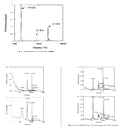
I am trying to convert my fft signal into PSD(Normalized) vs Freqeuncy (Hz) but can't get it right. I want to get some thing like shown in the figure. I found these figures in the literature. How to plot this in matlab? PSD from 0-1 and frequency in log scale.
psd.png

If some one can explain with a simple example, it will be highly appreciated
 

Hi,

X-axis:
You see it is a logarithmic scale. You need to start with a frequency larger than 0Hz (0Hz = DC is not possible)
In the top picture this is 1000Hz, in all other pictures it is 100Hz.
But this is somehow untypicial for an FFT output. An FFT output always starts with 0Hz (=DC) and has 2^n frequency taps with equal frequency distance. It is linear, not logarithmic.

Example: An FFT result of 1024 values sampled at 10.24kHz will give 512 results stating with 0Hz and an equal frequency distance of 10Hz = 10.240 Hz / (2 x 512)

****
Y-Axis.
Often this is in a dB scale.
In your top picture you see the referece signal. It is "normalized" to be in scale of "1" wich is 0dB.

I can´t see how the other diagrams are normalized. I expect either a reference signal (value = 1 or 0dB) or a fixed power like "1mW" which is 0dBm. But both is missing. Maybe they refer to the first diagram.

***

Klaus

How to plot this in matlab? can you give me a simple example? I am struggling in calculating a normalized PSD which range from 0-1 on y-axis?
 

Status
Not open for further replies.

Similar threads

Part and Inventory Search

Welcome to EDABoard.com

Sponsor

Back
Top