Continue to Site

Welcome to EDAboard.com

Welcome to our site! EDAboard.com is an international Electronics Discussion Forum focused on EDA software, circuits, schematics, books, theory, papers, asic, pld, 8051, DSP, Network, RF, Analog Design, PCB, Service Manuals... and a whole lot more! To participate you need to register. Registration is free. Click here to register now.

how to construct a DC motor circuit by changing the motor polarity using relay?

Status
Not open for further replies.

EESeeker

Junior Member level 1
Joined
Jun 20, 2011
Messages
17
Helped
1
Reputation
2
Reaction score
1
Trophy points
1,283
Activity points
1,402
i am currently doing a project which requires to control the DC motor. I would like change the DC motor polarity using relay.. but somehow i couldn't figure out...
thx for any guidance!=)
 

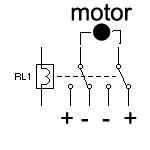
You can do it with a Double Pole Double Throw Relay (DPDT relay)
DPDT.gif

but you also need a switch to stop the motor because the relay will only be able to control the direction (polarity)

Alex
 

thx Alex...

but i got a problem is i supply the voltage source differently at the coil and switch in relay with 12 V ....but the voltage supply at motor still having 5 V only...why the voltage at the motor isnt 12 V and how to increase the voltage at the motor in order to increase the speed of motor?
 

If I understand correctly you are using 5v to control the relay coil and you are using 12v to the relay contacts and the motor.
Are you sure that you are using the correct pinout of the relay and that the relay you have has two independent switches?
Disconnect everything from the relay and provide just the 5v control voltage to the coil (it is a 5v relay right?), then measure each of the switch pind with reference to gnd and verify that none of them has any voltage.

Alex
 

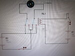
IMG_0331.JPG
this is my circuit.... as the two voltage supply is both 12V... but the motor turn up to be run as 5 V only...
 
You haven't used a ground so the voltages are not shown correctly in the simulation, add a gnd in the negative side of the batteries

Alex
 

oh ya....thx vry much~~!!! ya.. it works....^^

---------- Post added 21-06-11 at 01:20 ---------- Previous post was 20-06-11 at 23:39 ----------

i tried the attached circuit above to breadboard...but it seem to have short-circuited... do i need to concern on any criteria for running a DC motor or adding any extra components to the circuit?
 

You don't need any resistor assuming that the motor is a 12v motor and the relay coil is also for 12v.
Make sure that you have connected the relay correctly,if you don't know the pinout you can use an ohm meter, maybe you have used the gnd and +12v to the wrong pins and they short.
You can remove the motor and measure with a voltmeter the output of the relay in the same pins where the motor was connected.

Alex
 
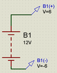
In a real circuit it wouldn't matter but in proteus it does, check the result with a 12v battery, there is nothing else in the circuit

battery_floating.gif

Alex
 

i would like to ask in Proteus, the circuit run well but there is sometimes having small red or blue square at the component ... wat does it means actually?
 

Pin Logic States:

"This option displays a colored square by each pin that is connected to a digital or mixed net.
By default, the square is blue for logic 0, red for logic 1 and grey for floating.
The colors may be changed via the Set Design Defaults command on the Template menu.
Enabling this option incurs a modest extra burden on the simulator, but can be very, very useful when
used in condition with breakpoints and single stepping as it enables you to study the state of a
micro-controllers output port pins as the code is single stepped."

Alex
 
i would like to run my motor for certain time only once my switch is close..is it appropriate to use monostable timer to set the time period for my motor to run after my switch in on? if so, when is my next trigger? is it nid to open the switch and close it again for the next trigger?
 

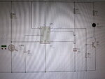
IMG_0332.JPG

this is a light sensor circuit with 555 timer....the timer is monostable timer and once the light is detected, the timer will be triggered and led will light up...
my problem is when the light intensity is getting higher the led light on as it should be, but when decreasing it, the led wouldn't light off when there is low or no light intensity.. why this happen? is it sth wrong wif my circuit?

p/s: i m using NPN for the output in order to connect with my relay in motor circuit above.

thx=)
 

i think i got it ald...again forgot to put a 'gnd' ...
 

The delay that you are using is about 5sec, did you wait enough for the output to turn off (simulation time).
Are you sure about the level in pin 2 is high enough so that it doesn't trigger?
The NPN shouldn't be a problem but you have to use a base resistor to limit the base current, try 1K

Alex
 

it din count 5 second although i nid 5 s for the led to light up once it detect light... i thought this software cant count the time for this... .

Light dependent resistor Engineering » LDR Engineering

the basic idea is come from this link first example which build a dark sensor with 555 timer... it showed in the video that this circuit worked... however, when i try to the real board, it din count 5 second aso..so is the circuit design wrong for the dark sensor with 555 timer?
 

Yes, the proteus model is not working correctly in that way, it turns on at the proper level of the input but in never turns off, the voltage at pin 6 should be showing the capacitor charge but it isn't
Maybe some other simulator has a model of 555 that actually works.

Maybe your LDR doesn't provide the proper level to the input for the circuit to go off, pin 2 is triggered to turn on when it is below 1/3 Vcc.
Remove the LDR and use a button as the schematic 555 and 556 Timer Circuits and check if you get the 5sec delay correctly (in a real circuit not simulation), if that works then try with the LDR

Alex
 
**broken link removed**
this attached schematic is used the light sensor to control the motor....as the light intensity is high(as the value is around 100) the motor only will rotate... but i have problem is even the light intensity is low the motor is still running.... i m using 12 V relay. so is it the apply voltage should be 12 V aso oni the relay work?
 

Status
Not open for further replies.

Part and Inventory Search

Welcome to EDABoard.com

Sponsor

Back
Top