Continue to Site

Welcome to EDAboard.com

Welcome to our site! EDAboard.com is an international Electronics Discussion Forum focused on EDA software, circuits, schematics, books, theory, papers, asic, pld, 8051, DSP, Network, RF, Analog Design, PCB, Service Manuals... and a whole lot more! To participate you need to register. Registration is free. Click here to register now.

how to connect to lcd 16x2

Status
Not open for further replies.

iVenki

Member level 3
Joined
Apr 2, 2011
Messages
60
Helped
0
Reputation
0
Reaction score
0
Trophy points
1,286
Activity points
1,771
I know that lcd 16x2 has 16 pins to which we have to give the connections.


My problem is that I don't know to give the connections. I see 16 holes near the label JHD 162A but I don't know how to give the connections because I am new to lcd 16 x 2. i.e. How do you connect to these holes as I have never done connections through holes before.

I am clear with the circuit diagram. I have no problem with that.


Please help me

thanks in advance.
 

you can either solder a ribbon cable

GreyRibbonCable.jpg

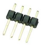
or I prefer a pin header
HEADS.jpg

Alex
 

Thanks. I saw the same thing in that image of lcd 16 x 2. I am going to use pin header. Okay. How do you connect pin header? Do you solder it or give connections directly?
 

solder the pins on the pcb and solder female housing for these headers on the LCD pins...

other way is to solder the shorter end of header pins to PCB , and longer end of pins to lcd... but you cannot remove or replace if it goes bad....

if you use male and female pins then you can remove it from the board.........
 
  • Like
Reactions: pawan5

    pawan5

    Points: 2
    Helpful Answer Positive Rating
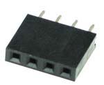
You can solder it if you want but it would be better to use a female header which can be easily disconnected.
FHEADS.jpg
It would also make it possible to easily connect the LCD to other MCU boards

Alex

P.S I usually use a cable between the mcu board and LCD (headers at the end of the cable) to be able to have a distance between them
 

I am gonna use the bread board first. Then is it necessary to solder the pins on the pcb? (because I am not using the pcb at all right now).

What are male and female pins?

Awaiting for your reply sir.
 

Female is shown in post #7 and male is shown in post #3.

If you are using the breadboard then you can solder a header to wires and insert the cable ends to the breadboard and then connect the header to the other header of the LCD

Alex
 

male and female are the picture shown by alex... you have to solder the pins to LCD or else it will be very loose and may not have contact.. you can do one thing...

you can solder female housing to LCD such that soldering is on the display side and female part of connector is on the bottom side...

then you can just insert the pins into the bread board and insert the female connector to the pins on the bread board... then you can take wires from the bread board where the header pin connector are fixed on the board.
 

    V

    Points: 2
    Helpful Answer Positive Rating
I am quite confused sir. I think I could understand better after seeing them. What should I buy? Should I buy 16 male and female headers?

---------- Post added at 16:32 ---------- Previous post was at 16:30 ----------

Which is better sir? Pin header or ribbon cable?
 

The headers come in different lengths, if you buy the one with 40 pins you can cut and use only 16 of them and keep the rest for future projects.

The ribbon cable is just a bunch of cables one close to the other, you can use individual wires if you want, the ribbon is just easier to manage.

The combination you are going to use is up to you, we have described every combination.

Alex
 

it depend on your application, if you want to fix your LCD to circuit board, then you can buy the header pin, then solder it at both side. if not, you can choose other connection type you want as long as it easy for you to plug/unplug/connect/disconnect your LCD.
 

Post 3 is berg stick... and post 7 is berg housing.... just go to the shop and tell you need single row berg stick and housing.. he will give one full length.. cut it to 16 pins....
similarly the female strip is called berg housing... cut it to 17 pins and pull out the 17th pin and retain 16 pins... then solder the female housing to LCD

keep lcd such that the display is towards top and insert the female housing from bottom... then you should see only pins of it on the display side... solder those pins from top of the lcd....

---------- Post added at 17:08 ---------- Previous post was at 17:06 ----------

ribbon cales are good but , they are delicate and if you dont take care of lcd placement or pull the wires then it may come out with the pads of LCD and if that happens then your LCD goes bad as you cannot resolder if pads comes out... better to solder the berg housing and use berg stick on the board and insert the housing into to berg stick......
 

What are male and female pins?

You know the difference between a male and a female?
A man has a pin, a woman a hole.
 

Status
Not open for further replies.

Similar threads

Part and Inventory Search

Welcome to EDABoard.com

Sponsor

Back
Top