danishdeshmuk
Advanced Member level 1
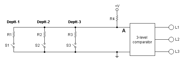
How to connect 3 different lights (indication) for 3 different deptts. in such a way that when alarm button is pressed in the respective deptt (department) the respective light turns on ?
Note : All the Alarm buttons are on-off switches and they are all (of every department) connected to each other ....
thanks
Note : All the Alarm buttons are on-off switches and they are all (of every department) connected to each other ....
thanks