Continue to Site

Welcome to EDAboard.com

Welcome to our site! EDAboard.com is an international Electronics Discussion Forum focused on EDA software, circuits, schematics, books, theory, papers, asic, pld, 8051, DSP, Network, RF, Analog Design, PCB, Service Manuals... and a whole lot more! To participate you need to register. Registration is free. Click here to register now.

[SOLVED] How to choose transistor power amplifier for a signal transmitter from unconventional specifications

Status
Not open for further replies.

Minchuu

Junior Member level 1
Joined
May 14, 2021
Messages
16
Helped
0
Reputation
0
Reaction score
0
Trophy points
1
Activity points
156
Hello!

I have a 4vpp signal at 500 kHz that needs to be transmitted at a max distance of 50km. Therefore, it needs to go through a transistor power amplifier that will also drive a 50ohm load (theoretically, the antenna). The bit rate will be 50 kbps. The receiver sensitivity at the end of the 50km distance is -50 dBm.

As a newbie student at this kind of topic, I am at lost how to choose what type of amplifier shall I choose, and what exactly am I designing. I apologize if I sound stupid TT^TT, but I cannot seem to connect how to choose the amplifier and what is the gain needed based from the weird specifications given. Also, everything will only be simulated so I don't need good results in real life, only that it works optimally in simulations.

Any guidance on this matter will be very much appreciated. Also, if you guys have any power amplifier analog circuit schematics that you can share that will do the bare minimum of the specifications, it will also be very much appreciated also.

Thank you very much!
 
Last edited:
You wish to broadcast on 500 KHz which is close to the spectrum of commercial AM stations. To be heard 50 km away those stations need a lot of power going to their antenna, and you'll also need substantial power. However if anyone picks up your signal (or overtone splatter due to unintended distortion) then you might get an unexpected "visit from local authorities". (Of course it depends on legal restrictions in the country where you live.)

It's important for you to get informed as to what's permissible and what's not. Consider broadcasting on the shortwave bands. If you broadcast on 500 KHz I would limit my signal strength to a short distance, say to the next room. And for a brief period, say a minute at a time.
Hi! Fortunately, or unfortunately depending on one's view, this project will only be simulated because of the remote learning due to the pandemic. So I need not to worry about permissions because we won't really broadcast in real life. I only need to operate this project on a purely theoretical basis.
 

If you google "rf path loss & transmission distance calculations" there are a number
of aids on web that should help.


Regards, Dana.
 

In general you apply a 500KHz sinewave (carrier frequency) to a length of wire (your transmitting antenna). Normally the antenna does not carry current. Instead it radiates a magnetic field at 500 KHz. I believe the understanding is that the field alternates between positive and negative polarity.

Under the right circumstances, when the signal is sufficient voltage and the antenna is physically built to the right length, or else electrically tuned to resonate at 500 KHz...

A transition occurs from a magnetic field to electromagnetic waves (i.e., photons, in the sense that radio is of a similar nature as light, both being electromagnetic waves).

The antenna consumes current. Photons radiate from the antenna. If it is constructed to be directional then the photons may be concentrated in a beam strong enough to be picked up by your receiver at 50 km distance.

The oscillating circuit needs to be stable at your desired carrier frequency. Often it's based around an LC tank. Common choices are Colpitts, Clapp, Hartley, Pierce.
 

    Minchuu

    Points: 2
    Helpful Answer Positive Rating
Antenna V and I distribution, dipole, monopole -

1621332170084.png


1621332191474.png


Field distribution -


Regards, Dana.
 

    Minchuu

    Points: 2
    Helpful Answer Positive Rating
Thank you for the discussion! I kind of got it, and from my research from the clues you gave me, I think I got was that I need a transmit power of 51 dBm. It does seem kind of a lot, though. Do you guys have any suggestions what topology of transistor power amplifier should I use to achieve this kind of dBm? Especially since my signal is only 4vpp.
 

Don't know how you arrived at 51 dBm. R&S field strength and power estimator gives me +66 dBm (4 kW) transmitter power for -50 dBm received power and antennas with dipole gain. These days, class D amplifiers are preferred for high power in medium wave range.
 

Don't know how you arrived at 51 dBm. R&S field strength and power estimator gives me +66 dBm (4 kW) transmitter power for -50 dBm received power and antennas with dipole gain. These days, class D amplifiers are preferred for high power in medium wave range.
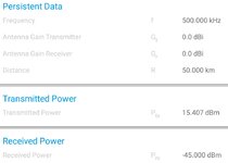
I set a link margin of 5dB, so the minimum signal power that the receiver should detect would be -45 dBm. I computed the path loss to be 60.4 dB if 50km is used with 500kHz operating frequency. so the transmit power is -45 dBm + 60.4 dB = 51 dBm.

But of course, I am really not sure about my methodology so you would probably be correct and thank you for the correction! :) I will try to design and simulate a class D amplifier. Very much appreciated!
-45+60.4 = 15.4 dBm

that is 1.3Vrms onto 50ohm load, corresponding to roughly 4Vpp, that is your specified voltage. If you can use a generator able to directly drive a 50 ohm load you have to do nothing, otherwise you'll need a transistor stage having gain=1 but able to match your impedance with the load.
Since is a simulated link I supposed no antennas gain and no losses due to cables.
--- Updated ---

All the transmitters I have seen are dark at night and do not produce photons (in post #5).
The word "photon" is related not only to the ligth, but to all the EM waves
 
Last edited:
whatever your power to the antenna, say 1W, the xtor will need to be rated well above this and properly heat sunk and will likely dissipate at least the same. i.e. in his case 1W, thus the power supply to this stage should be at least 3x capable, i.e. 3W in this case ...
 

Obtaining this power level is not an issue but the antenna dimensions are really troublesome.Because
\[\lambda\]=600m
 

-45+60.4 = 15.4 dBm

that is 1.3Vrms onto 50ohm load, corresponding to roughly 4Vpp, that is your specified voltage. If you can use a generator able to directly drive a 50 ohm load you have to do nothing, otherwise you'll need a transistor stage having gain=1 but able to match your impedance with the load.
Since is a simulated link I supposed no antennas gain and no losses due to cables.
--- Updated ---

oh, I think I did an arithmetic mistake, thanks for pointing it out. I think I got the 51 dBm because I was confused about the operations involving dBm and dB. 15.4dBm does sound more reasonable. We're not allowed to use generators, so I will probably do a Class D amplifier. But you're right, I'll have to spend effort with the impedance matching.

Thank you for all the help!
 

Status
Not open for further replies.

Part and Inventory Search

Welcome to EDABoard.com

Sponsor

Back
Top