Continue to Site

Welcome to EDAboard.com

Welcome to our site! EDAboard.com is an international Electronics Discussion Forum focused on EDA software, circuits, schematics, books, theory, papers, asic, pld, 8051, DSP, Network, RF, Analog Design, PCB, Service Manuals... and a whole lot more! To participate you need to register. Registration is free. Click here to register now.

how to choose the value of the feedback cap in switch-capacitor circuit

Status
Not open for further replies.

bsaqycx

Newbie level 5
Joined
Aug 5, 2009
Messages
10
Helped
0
Reputation
0
Reaction score
0
Trophy points
1,281
Activity points
1,343
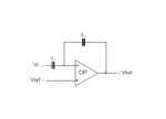
the opamp is used in switch-capacitor circuit and the gain is 1. However, how should I choose the value of C1?
Could C1 be considered to be the load of the amp? If so, the stability performance of opamp is affected.
If the opamp is a 2-stage miller-compensated op, which is the key point to the slew rate of this SC circuit, the driving ability of the opamp or the slew rate of the amp?
 

Attachments

  • pic.png
    pic.png
    3.5 KB · Views: 140

When you implement this using switch-capacitor technique, your amp would slew to charge the capacitances during switching transients. Anyway if your amplifier is unstable to this step requirement, then the output might saturate. This spike current's amplitude depends on C1.
 

Could C1 be considered to be the load of the amp? If so, the stability performance of opamp is affected.

A capacitor within the feedback loop of an inverting opamp does not reduce stability properties.
 
Could C1 be considered to be the load of the amp? If so, the stability performance of opamp is affected.

A capacitor within the feedback loop of an inverting opamp does not reduce stability properties.

So that means: the stability of SC circuit should be OK if the opamp is stable with the load, is it right?
 

So that means: the stability of SC circuit should be OK if the opamp is stable with the load, is it right?

Yes, I think so. However, where are the switches in your "S/C integrator"?
 

Yes, I think so. However, where are the switches in your "S/C integrator"?
For simplicity, the switches are ignored.
One more thing, it's written by some books that the feedback Cap (C1 )could be equivalent to the output load with (1-β)C1 (β is the feedback factor). If so, I think the feedback Cap would affect the stability of SC circuit.
 

For simplicity, the switches are ignored.
One more thing, it's written by some books that the feedback Cap (C1 )could be equivalent to the output load with (1-β)C1 (β is the feedback factor). If so, I think the feedback Cap would affect the stability of SC circuit.

Can you justify your "feeling"? More than that, in sampled data systems (like S/C circuits) there is no "feedback factor" as can it be defined in linear time continuous systems.
 

Can you justify your "feeling"? More than that, in sampled data systems (like S/C circuits) there is no "feedback factor" as can it be defined in linear time continuous systems.
I think S/C circuits also have their "feedback factor". You could find it in the "Design of analog cmos integrated circuit" written by Razavi and there're several thread about it (https://www.edaboard.com/threads/43229/).
 

I think S/C circuits also have their "feedback factor". You could find it in the "Design of analog cmos integrated circuit" written by Razavi and there're several thread about it (https://www.edaboard.com/threads/43229/).

OK, now I know what you mean. I think, we have to go back to some definitions (in order to avoid misunderstandings).
The term "feedback factor" originates from linear time-continuous control theory and, therefore, is applicable also to amplifiers with feedback. And in this context, this factor determines stability properties of the system.
Note that this factor either is constant (frequency independent) or depending on frequency. In the latter case the factor is defined in the frequency domain.
Now the question: Can this definition resp. this view be transferred to sampled data systems?
Generally spoken, I think: No, because S/C circuits are described in the z-domain.
However, there may be one exception (and that's what Razavi did): During one of the sampling phases (Razavi: "Amplification phase") one can treat the whole system as a linear and time continuos system and compute something like a "gain" in the frequency domain (s-domain). Although none of the signals are sinusoidal ! And for this linear/time continuos model - applicable only during one clock phase - you can define a "feedback factor" in the s-domain.
Why this approach? As far as I can see, only for the purpose to compute the step response (finding of the time constant of a first order system) during this particular phase.
But this does not mean that the whole S/C circuit is a feedback system with a "feedback factor".
(Remark: Don't blindly trust some answers/contributions in this or in other forums).
LvW

Hi LvW:
Thank you for your explanation and now I understand S/C circuit more deeply. As you said, the feedback factor could also be used during ONE phase of clock. Based on this, the amp should also be stable during this phase and the feedback cap could affect the stability from this view, right?
Is it usually taken into account when S/C circuit is built?
BTW, I'm new to S/C circuit and could you recommend some references to start.
Thank you for your kindly help!

Hi bsaqycx,

as I have mentioned earlier, don't be afraid of stability problems using "normal" and classical opamps.
It's not easy to recommend some s/c literature here. Of course, thre are some introductory books - however, by searching in the internet ("switched capacitor basics") you certainly will find some good articles.

Hi LvW:
Thank you for your reply ~~~
 

xcuse me. can any of you help me with read the capacitor code. i have a square-look cap with 1u0j100 writen on it. is it 1 nF? thx and sorry to ask it here.
 

Status
Not open for further replies.

Part and Inventory Search

Welcome to EDABoard.com

Sponsor

Back
Top