Continue to Site

Welcome to EDAboard.com

Welcome to our site! EDAboard.com is an international Electronics Discussion Forum focused on EDA software, circuits, schematics, books, theory, papers, asic, pld, 8051, DSP, Network, RF, Analog Design, PCB, Service Manuals... and a whole lot more! To participate you need to register. Registration is free. Click here to register now.

How to choose bias resistors for long tailed pair

Status
Not open for further replies.

Farad22

Junior Member level 2
Joined
Apr 10, 2015
Messages
23
Helped
0
Reputation
0
Reaction score
0
Trophy points
1
Activity points
212
Hi all,

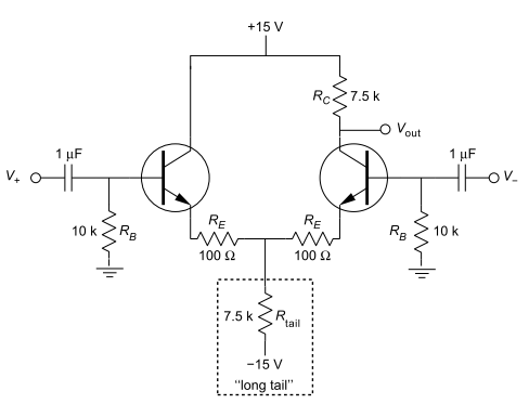
I have the following schematic attached of an AC-coupled differential pair. I would like to know how to choose the right value of the base DC bias resistors (Rb)? Many times I see values used between 10K - 100K. What factors decide how we should choose the value of these resistors? Thanks in advance.


The tail resistor creates the effect of causing one transistor to shut off as the other transistor turns on.

Its ohm value is adjusted so it shifts the output voltage into a desired range of response. For instance, so that 0V input produces 0V output.

- - - Updated - - -

Reading again I see your question is about biasing the transistors. I believe the 10k resistors are there to prevent a floating input, which would otherwise pick up ambient mains hum.

The resistors provide a current path to 0V ground for the input signals (which normally are ground-referenced).

We could also say the resistor forms a high-pass filter along with the DC blocking capacitor. However the filtering action may or may not be an intended feature of the design.
 
  • Like
Reactions: DanyR

    DanyR

    Points: 2
    Helpful Answer Positive Rating
    V

    Points: 2
    Helpful Answer Positive Rating
Hi,
...never thought about it much, I suppose you just use enough resistance to hold the transistor base off and stop it floating. It's just a rule of thumb, isn't it (1K/10K/100K) that most people use. The formula is somewhere in this book I bet...

'Though old, the book is nice to read/dip in and out of to get an understanding of many transistor issues, even if you ignore some of the endless calculations, it's helping me at least.

View attachment GE - Transistor Manual 1964.pdf
 
  • Like
Reactions: DanyR

    DanyR

    Points: 2
    Helpful Answer Positive Rating
    V

    Points: 2
    Helpful Answer Positive Rating
Thanks for your answers. That transistor manual looks interesting. I didn't find specific info in it about the factors that determine how to calculate these bias resistors. If anyone has more input on how to dimension these base resistors then please let me hear.
 

Thinking about it... If those resistors (Rb) are not just to tie the transistors to an appropriate logic level, then maybe it's a case of calculating the voltage required at the base, or to keep the input voltage below max. Vbe (~5 V), the way people use a 5V Zener diode?
 

The resistors Rb serve only one purpose: They must allow a bias current Ib between the base nodes and ground.
At the same time they are a part of the dynamic signal input resistance. Therefore they should be as large as possible, however, low enough not to cause a dc voltage drop that is too large.
That means: The value should be a trade-off between two conflicting requirements: A typical situation for analog electronics.
Hence. some values between 10k and 100k seem to be appropriate.

Example: For a collector current of 1mA and a current gain of the BJT`s of B=100 we have Ib=10µA. Thus, a value of Rb=10k would produve a dc voltage of 0.1V at the base node. This seems to be acceptable.
 
Status
Not open for further replies.

Similar threads

Part and Inventory Search

Welcome to EDABoard.com

Sponsor

Back
Top