mre22
Newbie
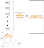
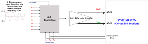
Since STM32MP157D requires positive analog input, I have added a fully differential amplifier to capture the negative inputs. STM32MP157D devices embed two analog-to-digital converters.
I have attached a diagram that explains my problem. I need to capture the 8 bipolar analog inputs simultaneously to get accurate phase information.
What is the best and optimal way of achieving this?
I have attached a diagram that explains my problem. I need to capture the 8 bipolar analog inputs simultaneously to get accurate phase information.
What is the best and optimal way of achieving this?