Continue to Site

Welcome to EDAboard.com

Welcome to our site! EDAboard.com is an international Electronics Discussion Forum focused on EDA software, circuits, schematics, books, theory, papers, asic, pld, 8051, DSP, Network, RF, Analog Design, PCB, Service Manuals... and a whole lot more! To participate you need to register. Registration is free. Click here to register now.

How to calculate the order of the filter

Status
Not open for further replies.

Monzerje

Junior Member level 3
Joined
Oct 22, 2017
Messages
28
Helped
0
Reputation
0
Reaction score
0
Trophy points
1
Location
Kuala Lumpur, Malaysia
Activity points
244
Hi guys
I am designing an analog bandpass filter, and I am trying to determine the order of the filter, but I do not know how to calculate the passband and stopband attenuations, and what are the passband and stopband frequencies. The filter details are mentioned below:
F1= 27.5 GHz
F2= 31.225 GHz
Fc= 29.3625 GHz
BW= 3.725 GHz
 

You can design a bandpass filter of any order that complies with the given specification. Without additional parameters for passband and stopband characteristic, neither the filter order nor the filter type (e.g. Butherworth, x dB Chebyshev. Elliptical etc. can be determined.
 

Thanks for your reply....
Now I can see the quick reply box. Anyway, I am designing a Chebyshev bandpass filter, by using microstrip method, therefore I need to calculate the order of the filter to determine the even and odd characteristic impedances to design the filter. So is there any formula that might help me to do that, because I can not just select any order randomly.
 

Without further specifications, why not select the lowest available order (one resonator)?
 

Thank you pancho_hideboo for ur comment, but I think those links can not help me to find the answer of my question.
 

Dear FvM since there is a formula to find the order, I prefer to choose that way as I do not like to give assumption in my project because it will decrease the work quality of the project. The only thing I need is how to find passband and stopband attenuations, passband and stopband frequencies, and I know to dertermient the order and proceed with next steps.
 

Thank you pancho_hideboo for ur comment, but I think those links can not help me to find the answer of my question.
I don't think so.
You provide center frequency and bandwidth.
So change order and ripple until you satisfy.

Estimation of order is valid for even and odd mode.

Dear FvM since there is a formula to find the order
There is no formula.
Iterations are needed.
 

Yes, there are formulas Capture.PNG, I took them from IEEE journals, but they require passband and stopband attenuations to calculate the value of X, and then I can find the filter order n.
 

Last edited:

No matter if using a formula or deriving the useful order by iteration, the problem is apparently that you don't have a pass band and stop band specification. But we can't know it either, it is set by the filter application.

To proceed with your exercise problem, you may assume an arbitrary specification, e.g. pass band ripple 1 dB, stop band frequencies f1-2 GHz, f2+2.5 GHz, attenuation 40 dB and apply your calculation method.
 
How to find the filter order by using graphical method

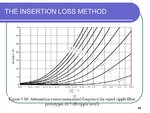
I am trying to find the filter order by using graphical method (insertion loss method) and when I calculate the value of (Wn) I am getting 0.976 and on the X axis of the graph it should be (Wn-1) so that will me a negative value. Also I tried to use the calculation method by using the formula shown in the figure below and I still can not get the answer since (Wn^2<-1)
Lower cutoff frequency f_1=27.5 GHz
Upper cutoff frequency f_2=31.225 GHz
Bandwidth = 3.725GHz
Passband frequency Ω_p= 27.5 GHz
Stopband frequency Ω_s= 31.227 GHZ
Passband attenuation ∝_p = 0.5 dB
Stopband attenuation ∝_s = 25 dB
THE+INSERTION+LOSS+METHOD.jpg
Capture.PNG
 

Re: How to find the filter order by using graphical method

You need to adjust your pass- and stop-band specifications. If you refer to the diagram, you need at least 10 % relative transition bandwidth to achieve 25 dB attenuation with a 10th order filer. Presently, you have about zero transition band, e.g. cut-off frequency 31.225, stop-band frequency 31.227. That's not feasible.
 

Re: How to find the filter order by using graphical method

My lecturer told me that the pass band and stop band frequencies should be too close to the upper and lower cutoff frequencies that is why I chose those values. So what this the method of choosing them?
 

Even if I changed their value I do not think it will get any effect since passband and stopband values are not considered in the calculation, where we only use upper and lower cutoff frequency values and the center frequency
 

One general comment: The classical and most efficient way for finding a bandpass function (order and pole/zero distribution) is to apply the lowpass-bandpass transformation.
That means: Based on specifies bandpass requirements you - at first - must transfer these parameters into a corrsponding reference lowpass.
Then you can use existing formulas for finding the necessary lowpass filter order to meet the requirements.
After determining the corresponding lowpass poles you again have to transfer these data into the bandpass area.
 
The diagrams shown in post #13 are in fact valid for 0.5dB Chebyshev low-pass filters and can't be applied to a bandpass without transformation.

Here are frequency responses for bandpass filters with parameters according to post #13 and 3, 5 , 7 and 10th order (calculated as number of complex pole pairs). The respective stop band frequencies are the points where your specified stop band attenuation of 25 dB is reached.

bandpass.png
 

Thank you LvW for your information
I have seen the lowpass to bandpass conversion method, but in that method they use the same filter specifications. So what do you mean by "at first - must transfer these parameters into a corrsponding reference lowpass" can you elaborate more please?
 

Status
Not open for further replies.

Part and Inventory Search

Welcome to EDABoard.com

Sponsor

Back
Top