Continue to Site

Welcome to EDAboard.com

Welcome to our site! EDAboard.com is an international Electronics Discussion Forum focused on EDA software, circuits, schematics, books, theory, papers, asic, pld, 8051, DSP, Network, RF, Analog Design, PCB, Service Manuals... and a whole lot more! To participate you need to register. Registration is free. Click here to register now.

How to calculate the capacitance using HSPICE?

Status
Not open for further replies.

mostafah67

Member level 1
Joined
Jun 2, 2013
Messages
39
Helped
0
Reputation
0
Reaction score
0
Trophy points
1,286
Activity points
1,575
i need to know the output capacitance in a output of each stage of a cmos ring oscillator, i know the capacitance is voltage dependent but i need a value for my calculation, i can calculate the capacitance by hand calculations (by using of formulas from digital integrated circuits,by john.M rabaey) but i don't know how they are close to the actual value!
is there a way that i can calculate the capacitance using HSPICE or another software?
 
Last edited:

I think, one simple method - independent on the particular circuit or system - is to simulate the frequency dependence of the output impedance (ac analysis for the correct bias point).
Feed a current (ac, 1 A) into the output and find the corresponding voltage at the output node, which is (for ac=1A) identical to the output impedance.
Start with very low frequencies (to determine thr real part) and find the frequency for which the phase shift is 45 deg. At this point both parts (real and imag.) are equal.
 
There is a very easy way to calculate the effective gate capacitance, say for a FO4 chain. I could give a detailed description here, but it would be better for you to just go through the Circuit Simulation Chapter in CMOS VLSI Design: A Circuits and Systems Perspective by Weste and Harris. The basic idea is to make a FO4 inverter chain, and in one of the branches, replace the transistor with a dummy capacitor. HSPICE has an optimization routine which can change the capacitance value to match the fall/rise time of the inv-chain. Once the optimization converges, the dummy cap value will give you the equivalent gate capacitance of the inv-stage. The HSPICE script and explanation is given in the textbook. Also, I'd highly recommend this book for learning VLSI, it has relevant design examples and more useful explanations compared to Rabaey.
 
There is a very easy way to calculate the effective gate capacitance, say for a FO4 chain. I could give a detailed description here, but it would be better for you to just go through the Circuit Simulation Chapter in CMOS VLSI Design: A Circuits and Systems Perspective by Weste and Harris. The basic idea is to make a FO4 inverter chain, and in one of the branches, replace the transistor with a dummy capacitor. HSPICE has an optimization routine which can change the capacitance value to match the fall/rise time of the inv-chain. Once the optimization converges, the dummy cap value will give you the equivalent gate capacitance of the inv-stage. The HSPICE script and explanation is given in the textbook. Also, I'd highly recommend this book for learning VLSI, it has relevant design examples and more useful explanations compared to Rabaey.
I am VERY grateful to you:p.your answer was very usefull for me and i read that book and i got the main strategy for evaluating the capacitance in that way,

Capture.JPG

we must change cdelay until the measured delay between nodes c to d is equal to delay between c to g, and then the amount of cdelay will equal to the effective load capacitance at the input of X4, it is very interesting!
but i coudn't understand the optimzation method used in hspice:
Capture.JPG
if is possible please explain these part that how can we evaluate the optitmum capacitance. thanks again
 

HSPICE has its own optimization routine. All you need to do is initialize it with .model optmod statement. itropt=30 says it'll run 30 iterations to find your target value. Since the two measure errorR and errorF (rise and fall time error) goals are set to 0, HSPICE will change the dummy cap to minimize the delay between the chain of gates and that across the dummy cap. It'll stop after 30 iterations if the goal is not reached (0 difference in delay). If you look at the initialization of the dummy cap value, it is in brackets with (initial value, min value, max value) format, so that HSPICE knows where to start its optimization from and what range of cap values to use.

The optimization routine helps you get to a gate cap equivalent value faster than manually tweaking the value to get a match.
 
thanks very much again for your answers,it helped me
i have a ring oscillator with a VCTRL (control voltage) that control the oscillation frequency, i want to change the temperature (for example by .temp syntax) and then change the control voltage until the oscillation frequency return again to the initial value, can i use hspice optimization to find the vctrl values for each temperature so that the oscillation frequency be stable? would you please help me how can i do it? i really need that to continue my work.
 

thank's again for your good answer, i do the optimization and i obtain a value in hspice output equal to 119f, now i don't know what is this amount exatly? the gate effective capacitance or cpermicron?
i need the total load capacitance of inverter, i read in the book that we must set all of the AD,AS.PD.PS=0 in order to hspice only measure the gate capacitince (and not parasitic capacitance). in my case that i need the total gate capacitance shoud i also set the gate source area and perimeter to zero?
totaly i need to obtain total load capacitance of inverter and i don't know what is this capacitance is that hspice measures. please help me again,thanks
 
Last edited:

i really expect somebody answer me:sad:
since nobody answers i did my own things, first i set AD,AS,PD and PS to zero and then increase the input trigger pulse width such that the inverters can response correctly to the input pulse and hspice can correctly measures invf,capf,invR and capR times (but still there is a small amount of error between delays of c to D and c to g). then i multiply the obtained value of 'cpermicron' to the total width of gait (Wn+Wp) and i hope that the capacitance i obtain in this way was true:-(
 

Hello mostafah67!

Could you use a function for time derivation in HSpice?
I made some experiments in PSpice but as you can see in the attachments, only the inputs have a meaning capacitance values. I can't find, how to measure the outputs with same manner.
By the way, you can reed more about it in "A Nonlinear Capacitor Model for Use in the PSpice Environment".

Best regards, Feri

Sorry for my English.
 

Attachments

  • SCHEMATIC.pdf
    31 KB · Views: 214
  • SCHEMATIC_Sig's.pdf
    27.5 KB · Views: 194
Hello mostafah67!

Could you use a function for time derivation in HSpice?
I made some experiments in PSpice but as you can see in the attachments, only the inputs have a meaning capacitance values. I can't find, how to measure the outputs with same manner.
By the way, you can reed more about it in "A Nonlinear Capacitor Model for Use in the PSpice Environment".

Best regards, Feri
Sorry for my English.

hello and thanks very much dear pferenc
i saw your attachments, i think the basic principle used in your method and for mine is same, i can exactly understand the basics of method is used for measuring a effective equivalent capacitance for output of inverter, but i have a problem with spice deck, specially in this line(highlighted section):


1.JPG

i don't know which value i must multiply to the cpermicron for obtaining cdelay, i multiplied cpermicron to (wn+wp) of inverter and obtain CL, but when i used it to calculate the fosc of a ring oscillator according to this formula:
fosc= (Isource)/(N.CL.VDD) the result was wrong and real fosc (from measurement) was about twice the amount i expect from formula, and i think the capacitance value 'CL' that i used was wrong, please somebody guide me !

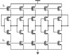
ring oscilator which i used:
RO.JPG
 

Status
Not open for further replies.

Part and Inventory Search

Welcome to EDABoard.com

Sponsor

Back
Top