Continue to Site

Welcome to EDAboard.com

Welcome to our site! EDAboard.com is an international Electronics Discussion Forum focused on EDA software, circuits, schematics, books, theory, papers, asic, pld, 8051, DSP, Network, RF, Analog Design, PCB, Service Manuals... and a whole lot more! To participate you need to register. Registration is free. Click here to register now.

How to calculate Power factor using Microcontroller ?

Status
Not open for further replies.

pic.programmer

Advanced Member level 3
Joined
Aug 19, 2015
Messages
773
Helped
141
Reputation
284
Reaction score
140
Trophy points
43
Activity points
7,531
How to calculate Power factor using Microcontroller ?

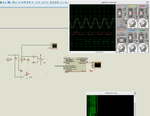
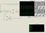
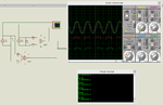
Should I use two ZCD circuits, one for voltage and another for current and sense ZC of voltage and start timer and then when ZC of current is detected then stop timer and convert the time delay value to angle and calculate the angle's cos to get power factor ?
 

I have made this project but it is not giving exact value for power factor. I have used PIC18F26K22 with 20 MHz external crystal. I have created a 250us Timer Interrupt. The yellow signal's ZC signal is fed to INT0 and blue signal's ZC signal is fed to INT1. When INT0 detects low to high, INT0 is disabled and Timer is started and INT1 is enabled. When INT1 detects low to high then Timer is stopped and INT1 is disabled. The processing of data is done and the result is displayed on UART.

The blue signal starts 2ms after yellow signal. Calculation is as follows. I have checked the value of count and it is 7 when there is 2ms difference between the signals.

Timer preload value is 64286.

count = 7 means 7 * 250us = 1.75 ms has elapsed.

If TMR1H << 8 + TMR1L contains 65536 then 65536 - 65536 = 0 and 1250 - 0 = 1250.

1250 is the difference between 65536 and timer preload value.

Clock is 20 MHz and hence each timer tick = 1 / (5 MHz / 1) = 0.2 us.

So, for 1250 ticks time will be 250 us.

1.75 ms + 250 us = 2 ms.

But I am not getting 2 ms exact value and hence angle and power factor values are wrong. What am I doing wrong ?


I have made the code based on this document.

https://www.ijeit.com/Vol 3/Issue 4/IJEIT1412201310_48.pdf

It mentions phase angle = (delta T / T) * 360

and cos phi = cos(phase angle)

Edit:

See the virtual terminal output in the attached image. It shows that value of count is 7 and value of TMR1 is 65426. So,

7 * 250us = 1.75ms and

65536 - 65426 = 110 and

1250 - 110 = 1140

So, 1140 timer ticks will be elapsed. Each tick takes 0.2 us

So, 1140 * 0.2 us = 0.000228 sec = 228 us

1.75 ms + 228 us = 0.001978 sec which is approx 2 ms

so for 0.001978 I have to get angle of

(1.978ms/20ms) * 360 = 35.604 degrees

cos(35.604) = 0.81306012

but the virtual terminal window shows some -5.x as the power factor. What am I doing wrong ?
 

Attachments

  • Power Factor Measurement.rar
    199.2 KB · Views: 119
  • Power Factor Measurement.png
    Power Factor Measurement.png
    121.4 KB · Views: 142
  • Power Factor Measurement rev1.rar
    321.2 KB · Views: 130
  • PF Measurement.png
    PF Measurement.png
    104.7 KB · Views: 108
Last edited:

count = 7 means 7 * 250us = 1.75 ms has elapsed.

We can try to eliminate all uncertainty about how our counting routine functions, but it always seems to insist on giving us a result that is off by 1.

Therefore with 7 as your result, your uncertainty is 14.3 percent. Your precision should improve if you were to count up to a larger figure. Did you try experimenting with longer cycles? Etc.
 

@BradTheRad

Longer cycles what ? Do you mean I have to use timer interrupts of 500 us and 1 ms ? but the count and TMR1 are holding correct values (values which give 2 ms). Then why I am not getting the power factor value correctly ? Is there anything wrong in the calculations ?
 

Longer cycles what ? Do you mean I have to use timer interrupts of 500 us and 1 ms ? but the count and TMR1 are holding correct values (values which give 2 ms).

Not necessarily different interrupt intervals, but a change in some value that will yield a higher count result. Say you get a count of 50, and your uncertainty is plus or minus 1. That gives you 2 percent precision, which is pretty good. If you try this, and if it does indeed work out this way, then it means you were not entirely incorrect in your method of calculating.
 

Hi,

Your circuit shows a clean sine. In reality you need precise filter to get rid of the overtones. Mind that the filter causes phase shift. To compensate for this you need exactly the same filter in both signals. In case of a deviation you could calibrate this with software.
The next problem in reality the voltage is about constant, but the current may vary. You need a minimum current for the comparators to work properly.
******
One analog type solution for phase shift measurement is to XOR both comparator signals. Then use a low pass filter to get a DC voltage to be measured with an ADC. Zero voltage means no phase shift, full Vcc means 180 degree phase shift. Half Vcc means 90 degree. If you need to know leading or trailing you could use a DFF, clock to one comparator, D to the other comparator. Q is leading/trailing information.
*****
To your solution.
Instead of using an interrupt and count in 0.25ms steps, you could use the capture feature. It gives way better resolution.
*****
For sure sampling both analog channels with an ADC, running a DFT on both channels and calculating the phase shift is the most precise solution. It is also independent of waveforms. I ft en done this with AVR, so it should be possible with PIC.

Klaus
 
Your circuit shows a clean sine. In reality you need precise filter to get rid of the overtones.
Only if you want to measure displacement power factor selectively. But the power factor of switched mode and transformer power supplies with rectfier is dominated by harmonic distortion and can't me measured with the intended setup.
 
Hi,

True.
The best example is a phase controlled (triac) ohmic load.
The load is purely ohmic. No reactive power when U(t) * I (t) is never negative.
Cos (phi) = 1
Although you will find that (filtered) voltage and (filtered) current have a phase shift.

Klaus
 

I will answer to all your responses soon. As of now here is my latest code. I changed the count variable from unsigned long type to double type and I am getting some other strange value.

In the interrupt routine time taken to execute (start timer after INT0 is detected) is 2.4 us and hence I have added 2.4 us in the total time calculation.

After INT0 and before the Timer is started 2,4 us will be elapsed hence the addition.

I don't understand from where it is producing a negative value for power factor.

Code:
if(INT0IF_bit) {
        INT0IF_bit = 0;
        InitTimer1();
 

Attachments

  • Power Factor Measurement rev2.rar
    302.5 KB · Views: 113
  • PF Measurement rev2.png
    PF Measurement rev2.png
    103.4 KB · Views: 80

I will answer to all your responses soon. As of now here is my latest code.

I see that the discussion about displacement or distortion power factor is not referring directly to your question. Perhaps we should postpone it for the time being. Of course you should be able to calculate a power factor for the shown waveforms.

I believe your calculation has errors. Probably not the reason for getting a negative values, but the cos() function argument is in radians, not degree.
 

Thank you FvM. Converting the angle to radians solved the problem.
 

Thank you FvM. Converting the angle to radians solved the problem.

pls do you mind showing a snippet of how you converted the angle to radians?...from this point below

"(1.978ms/20ms) * 360 = 35.604 degrees

cos(35.604) = 0.81306012"

thanks in advance
 

Google showed

1 degree = 0.0174532925 radians

So, I multiplied like this

cos(angle * 0.0174532925)

Indeed

cos(35.604 * 0.0174532925) = 0.81306012
 
  • Like
Reactions: sequel

    sequel

    Points: 2
    Helpful Answer Positive Rating
Hi

Angle --> radians
360° = 2 × Pi

Klaus
 

with something like this...

(7.912ms/20ms) am getting a negative value....pls am i getting the right value or something is wrong somewhere
that is to say

(7.912ms/20ms) * 360


cos(142.416 * 0.0174532925) = -0.792

is this a right power factor and can i have a negative power factor....thanks once again in advance

- - - Updated - - -

Hi

Angle --> radians
360° = 2 × Pi

Klaus

could you please explain....using this as a reference

(1.978ms/20ms)....to power factor

thnks
 

Hi,

Since cos is symmetric to the y axis the result could be positive and negative.

You may have leading and lagging phase angle.

360° = 2 × Pi is just the calculation factor 0.0017...

Klaus

Edited: corrected into "y axis"
 
  • Like
Reactions: sequel

    sequel

    Points: 2
    Helpful Answer Positive Rating
Power factor is 0.99905913150371730104370998352751

cos ((7.912ms/20ms) * 360) * 0.0174532925) = 0.99905913150371730104370998352751
 

Google showed

1 degree = 0.0174532925 radians

So, I multiplied like this

cos(angle * 0.0174532925)

Indeed

cos(35.604 * 0.0174532925) = 0.81306012

with something like this...

(7.912ms/20ms) am getting a negative value....pls am i getting the right value or something is wrong somewhere
that is to say

(7.912ms/20ms) * 360


cos(142.416 * 0.0174532925) = -0.792

thanks once again in advance

- - - Updated - - -

@ pic.programmer....

does it mean that with a longer delay the power factor increases?...
because i was looking at it from another side

that is to say with this below

"(1.978ms/20ms) * 360 = 35.604 degrees

cos(35.604) = 0.81306012"

and

cos ((7.912ms/20ms) * 360) * 0.0174532925) = 0.99905913
 

Status
Not open for further replies.

Similar threads

Part and Inventory Search

Welcome to EDABoard.com

Sponsor

Back
Top