Continue to Site

Welcome to EDAboard.com

Welcome to our site! EDAboard.com is an international Electronics Discussion Forum focused on EDA software, circuits, schematics, books, theory, papers, asic, pld, 8051, DSP, Network, RF, Analog Design, PCB, Service Manuals... and a whole lot more! To participate you need to register. Registration is free. Click here to register now.

How to calculate leakage and dynamic power for a circuit in Hspice

Status
Not open for further replies.

lokeshgarg

Newbie level 5
Joined
Jun 8, 2011
Messages
10
Helped
0
Reputation
0
Reaction score
0
Trophy points
1,281
Activity points
1,353


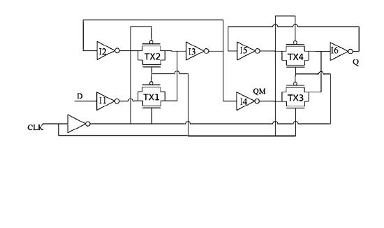
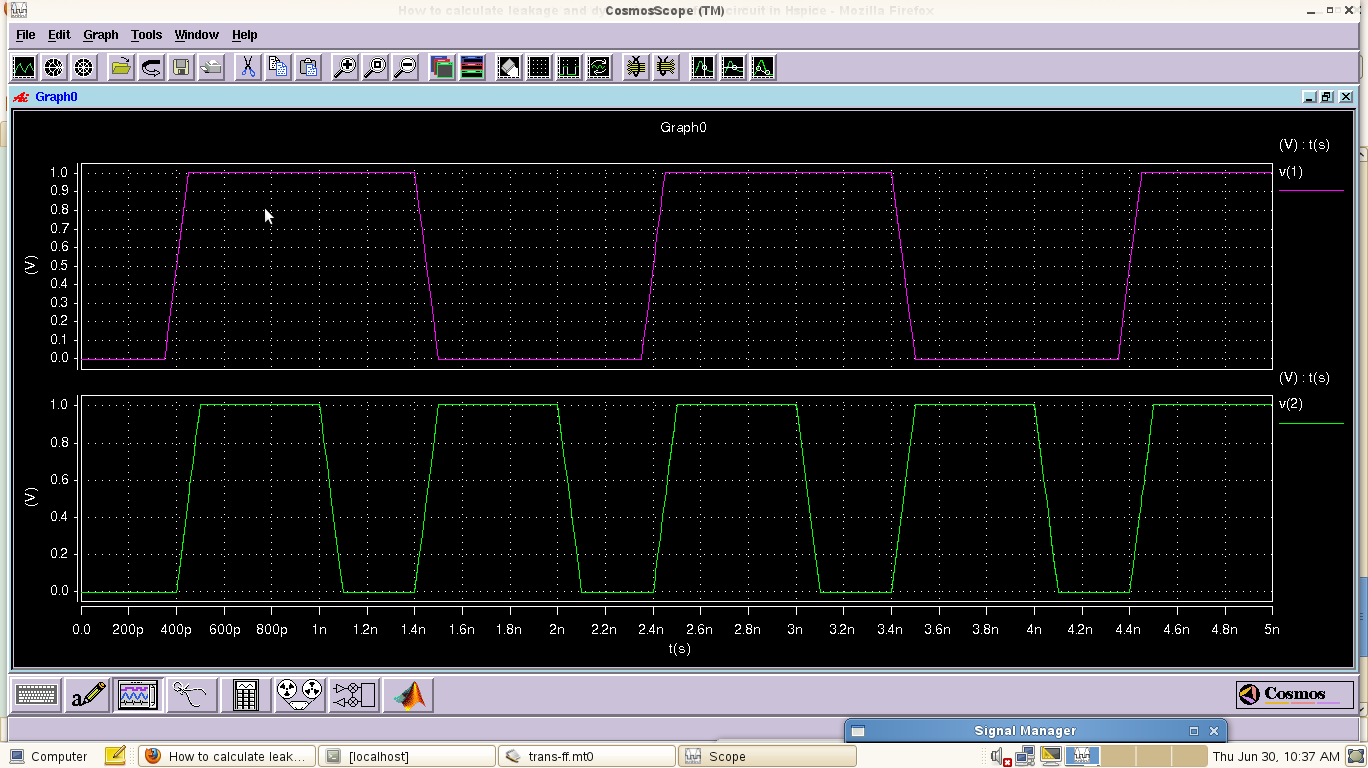
This is my circuit for which I want to calculate leakage and dynamic power.


thanks
 

It is d flip-flop. Its dynamic power consumption depends on CLK's frequency. Higher frquency leads to higher power consumption.
It comes from gate capacitor charging and discharging.

Also D signal also affects power consumption.

It is better to have simulation for better estimation.
 

Thanks for your ans.... but how to simulate this circuit & what should be the input values for calculation of leakage and dynamic power.
 

Add supply voltage source first. Set supply voltage for practical application.
Add periodical signal for CK.
If you are not sure about the application, just connect QB to D as 1/2 frequency divider.
Here, QB is input of I6.
And run HSPICE and probe the current of the supply voltage.
 

I am not able to understand your answer. If you can elaborate your answer, it would be better for me.... can i calculate leakage power if i connect 0 to both clock and input and then calculating current across Vdd???????
 

You must use dynamic signal to obtain dynamic current consumption.
However, devices in deep sub-micron process also has static current leakage.
 

Should I calculate leakage power for all the conditions i.e. D,clk = 00,01,10,11 and then take the average of all the currents????????????
 

If supply voltage is constant, you can use average current multiflying voltage to get the power.
Otherwise, you should integrate product of current and voltage thru time for average power.
 

Thanks for your reply.... i wanted to ask one more thing related to dynamic power. the circuit for i want to calculate power is positive edge triggered D filp-flop. when we will apply waveforms at D-input and clock, there may be the conditions in one clock cycle when clock is zero and input is switching. i want to ask that power related to this condition will be considered as dynamic power or not????
 

Yes, it will be considered as dynamic power consumption too.
 

I am having Problem with my code that total power consumed in one clock is less than the leakage power. This means that dynamic power consumed in that clock will come negative. I m attaching the code and waveforms....(upper waveform is input & lower waveform is clock)

vdd 12 0 dc 1v

***********Delay Calculation********************
vin 1 0 ac pulse(0v 1v 0.35ns 0.1ns 0.1ns 0.95ns 2ns )
vclk 2 0 ac pulse(0v 1v 0.4ns 0.1ns 0.1ns 0.5ns 1ns )
************************************************
***********Leakage Power Calculation(in,clk = 1,1)********************
*vin 1 0 dc 1v
*vclk 2 0 dc 1v
**************************************************************
*inverter1*
mni1 4 1 0 0 nmod w=90nm l=50nm
mpi1 4 1 12 12 pmod w=180nm l=50nm

*inverter2*
mni2 5 7 0 0 nmod w=90nm l=50nm
mpi2 5 7 12 12 pmod w=180nm l=50nm

*inverter3*
mni3 7 6 0 0 nmod w=90nm l=50nm
mpi3 7 6 12 12 pmod w=180nm l=50nm

*inverter4*
mni4 8 7 0 0 nmod w=90nm l=50nm
mpi4 8 7 12 12 pmod w=180nm l=50nm

*inverter5*
mni5 10 11 0 0 nmod w=90nm l=50nm
mpi5 10 11 12 12 pmod w=180nm l=50nm

*inverter6*
mni6 11 9 0 0 nmod w=90nm l=50nm
mpi6 11 9 12 12 pmod w=180nm l=50nm

*inverter-clock*
mniclk 3 2 0 0 nmod w=90nm l=50nm
mpiclk 3 1 12 12 pmod w=180nm l=50nm

*transmission-gate1*
mnt1 6 3 4 0 nmod w=180nm l=50nm
mpt1 4 2 6 12 pmod w=360nm l=50nm

*transmission-gate2*
mnt2 6 2 5 0 nmod w=180nm l=50nm
mpt2 5 3 6 12 pmod w=360nm l=50nm

*transmission-gate3*
mnt3 9 2 8 0 nmod w=180nm l=50nm
mpt3 8 3 9 12 pmod w=360nm l=50nm

*transmission-gate4*
mnt4 9 3 10 0 nmod w=180nm l=50nm
mpt4 10 2 9 12 pmod w=360nm l=50nm


.lib "45nm-bulk" cmos_models

.tran 1ps 5ns
.plot tran v(2) v(11)

************total Power Calculation(op =High)*****************
.meas tran itotal AVG i(vdd) FROM=0.4ns TO=1.4ns
.meas Etotal PARAM='-1*itotal'
**********************************************************
*.op
.option post
.probe
.end


Even if your simulation is correct, it can't be concluded as that. When you simulate dynamic condition, the voltage condition is not exact as that for leakage power simulation. So it is possible leakage power in dynamic condition is smaller than that in static case.
 

Status
Not open for further replies.

Part and Inventory Search

Welcome to EDABoard.com

Sponsor

Back
Top