Continue to Site

Welcome to EDAboard.com

Welcome to our site! EDAboard.com is an international Electronics Discussion Forum focused on EDA software, circuits, schematics, books, theory, papers, asic, pld, 8051, DSP, Network, RF, Analog Design, PCB, Service Manuals... and a whole lot more! To participate you need to register. Registration is free. Click here to register now.

[SOLVED] how to buil a power supply on pcb

Status
Not open for further replies.

fareen

Full Member level 3
Joined
Oct 31, 2010
Messages
154
Helped
4
Reputation
8
Reaction score
4
Trophy points
1,298
Activity points
2,193
hello
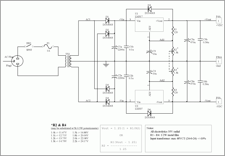
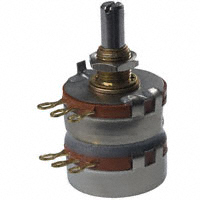
i need to design a variable dual power supply on a pcb.
the output supply should be plus and negative 15v and current rating of 800mv
i have no idea how to design it,i look at sum circuit on net but didnt get the idea
can sum one help me??? :roll:
 

Variable voltage regulator like LM317 should do the trick.

Google it, there are plenty of schematics/projects done with it.
 

The design and be done with one LM317 (positive voltage regulator) and one LM337 (negetive voltage regulator). The outputs then may be synchronided by the use of Dual potentiometers for the adjustment pins and fine tunned with a low value pot in series. Every detail of the design may be dound on the datasheet of the two said devices.
 
Hi,
Take a look at this:
94_1288606627.gif


The circuit is fairly standard of a linear supply, and the function of each part can be described as follows:

* TX1 is a center-tapped transformer which converts the line voltage from 120 or 240VAC to a lower value which can be managed by the filter circuitry.
* Diodes D1-D4 rectify the AC from the transformer output into a pulsing DC waveform. A bridge rectifier may also be used.
* Capacitors C1a and C2a are large electrolytics which perform bulk filtering duties of the pulsing DC waveform into a raw DC voltage. C1b and C2b are small film capacitors bypassing the electrolytics to improve transient response and filter high frequency line noise.
* U1 and U2 are the complementary adjustable voltage regulators LM317 (+) & LM337 (-). The output voltage may be programmed easily with two external resistors.
* Resistors R1-R4 set the regulated output voltage. The LM317 & 337 regulators develop 1.25V across R1 and R3, respectively. This reference voltage causes a constant current to flow through the voltage-setting resistors R2 and R4 which generates an output voltage approximately equal to the given relationship. R2 and R4 are two parts of a pot.
* Capacitors C3 and C4 improve the regulators’ ripple rejection from 65dB to 80dB (typical) by preventing ripple voltage from being amplified at the output of the regulator.
* Capacitors C5a and C6a are electrolytics that stiffen the output voltage and reduce output impedance. Capacitors C5b and C6b are small film bypass caps (similar to those at the regulator input) to filter any high frequency noise present at the output. The size of the four bypass capacitors is not particularly critical–the most important quality being they have reasonably low impedance at high frequencies, which is true of virtually all modern polyester, polypropylene, polystyrene, or mylar film capacitors.
* Fuse is required for short circuit protection.
* Switch is required for controlling the on/off of the power supply.
* Finally, D5 and D6 protect the regulator from damage in the event the input is shorted. Lacking these, the output capacitance can dump its charge instantaneously through low impedance paths internal to the regulators. The diodes bypass the regulator and allow the charge to safely dissipate.

1A 48VCT (24-0-24) transformer is about the practical upper limit of commonly available models. This limit is set by the maximum input voltage of the regulators, and also by the bulk filter capacitors which are rated at 35VDC. Actually, these are floating regulators so they can withstand considerably higher input voltages as long as the input-output differential does not exceed 40V. Select a transformer which will output a slightly higher peak AC voltage than the DC voltage you expect to obtain from the power supply. Recall that peak AC voltage is 1.414 times higher than the RMS value specified by the transformer.

Source: Linear Regulated Dual Polarity Power Supply by LM317 and LM337 | Circuit Project Electronic

My text has been slightly modified to suit your requirement.

Hope this helps.
Tahmid.
 
pranam77

"The outputs then may be synchronided by the use of Dual potentiometers for the adjustment pins and fine tunned with a low value pot in series."
i didnt get the idea you are trying to give
plz can you explain in more detail
 

Re: how to build a power supply on pcb

A dual potentiometer gangs two potentiometers together so that they operate in tandem.
Like this...
43_1288635016.jpg


This would be used as R2 and R4 in the schematic Tahmid supplied.
 

Tahmid
hi
the circuit u have given above is the kind i was looking for but i got sum issues
=i tried to simulate the circuit at multisim a unknown error occur that i can not amend:?
=i want to limit the out put voltage between -15 to +15 volts
the variable resistors has 1.25v across it and regulator give 32v output voltage
to adjust the voltage should i increase voltage drop across r2 and r4 or the other pair????
and i want the output current to be 800mv,for this what should i do????
 

pranam77
"The outputs then may be synchronided by the use of Dual potentiometers for the adjustment pins and fine tunned with a low value pot in series."
i didnt get the idea you are trying to give plz can you explain in more detail
The schematic given by Tahmid is the exact idea what i mean. As you can see the two variable resistors connected to the Adj pins of the Ics' have been ganged to move both Pots at a time. The picture of a dual pot is posted by "djsfantasi". In addition to that, my idea is to connect another variable potentiometer may be of 50-100 Ohms so that apart from the "Coarse" value set the the Main (Dual) pot, each of the Negetive and Positive volatges may be fine tunned using the secondary pots usually called as "Fine".
Cheers
 
Hi fareen,
As you can see in the diagram, its is provided that 1.3k resistance will provide 14.8v. So if you need exactly 15, try 1.4k if you can get it, otherwise you can make do with 1.3k or 1.5k.
The LM317 and LM337 can easily handle 800mA current, they can handle upto 1.5A.
Remember to mount them on proper heatsinks.

Hope this helps.
Tahmid.
 
hello
does anyone has a experience with multisim???
the circuit tahimd has given above im unable to simulate it.its giving unknown device error and sumtime the time step are too small cant debug the error.
can anybody help me??/
and tahimd thanks for the circuit its quite helping:)
 

Status
Not open for further replies.

Part and Inventory Search

Welcome to EDABoard.com

Sponsor

Back
Top