Continue to Site

Welcome to EDAboard.com

Welcome to our site! EDAboard.com is an international Electronics Discussion Forum focused on EDA software, circuits, schematics, books, theory, papers, asic, pld, 8051, DSP, Network, RF, Analog Design, PCB, Service Manuals... and a whole lot more! To participate you need to register. Registration is free. Click here to register now.

How to attenuate current in a wide range

Status
Not open for further replies.

eigen

Newbie level 3
Joined
Aug 4, 2014
Messages
3
Helped
0
Reputation
0
Reaction score
0
Trophy points
1
Activity points
40
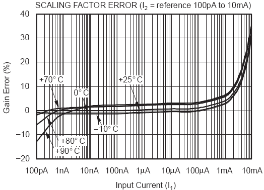
I need to measure a time-dependent current signal between 1uA and 20mA. I used a current log amplifier LOG114 from TI. It worked okay for low current level. But as long as the current passed 1mA, there were significant errors/nonlinearity, and the suggested error correction method in LOG114's manual was not good enough. So I am thinking of attenuating the current by at least 20 times to make LOG114 perform in comfort zone. Can anyone suggest a way of doing this, or alternative solution to this problem?
 

I looked at the datasheet if you are using the Dual Supply Configuration then it is easy. Since the input is the inverting input of the opamp the voltage there is always 0V so the current into 20R is 20 times less than the current into R. You can use R=100 ohm
 

Not a good idea. Current divider resistors will ruin the accuracy at lower currents. Increasing error above 1 mA shows that log transistor area is too small. A log amplifier with "larger" transistors, probably a combination of suitable transistor arrays and precision OPs may the only solution.
 

Fig 2 in the datasheet shows 8 decades of performance on a single supply.
V+ = 5V
 V− = GND
 100pA ≤ Input signal ≤ 10mA

What's different?
The error curve tells what the problem is.


Not a good idea. Current divider resistors will ruin the accuracy at lower currents. Increasing error above 1 mA shows that log transistor area is too small. A log amplifier with "larger" transistors, probably a combination of suitable transistor arrays and precision OPs may the only solution.

FvM,
If eigen comes back and say that my suggestion works, will you eat your hat?
 

The error curve tells what the problem is.


So if the desired accuracy is say 3% then only 6 decades of range are available and 4.5 decades of range are required.
So dropping the current by < 2 decades or /60 seems like a reasonable solution.

I'm not sure if the noise current in the resistor would be a problem for desired bandwidth.
 

If eigen comes back and say that my suggestion works, will you eat your hat?
No risk that it could "work". A short look at the input offset specification is sufficient to understand why. E.g. 4 mV/100 ohm = 40 µA current error.
 

from datasheet
Voltage inputs may be handled directly by using a low-impedance voltage source with series resistors,
but the dynamic input range is limited to approximately three decades of input voltage. This limitation
exists because of the magnitude of the required input voltage and size of the corresponding series resistor.
For 10nA of input current, a 10V voltage source and a 1GΩ resistor would be required.


So what voltage is the current source?
 

Status
Not open for further replies.

Similar threads

Part and Inventory Search

Welcome to EDABoard.com

Sponsor

Back
Top