sissi
Member level 4
hi
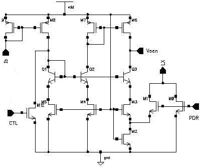
there is a current sense circuit of boost converter. but i dont know the theory. M0 is the power transistor while M1 is a sensing transistor,the size ratio of m0 to m1 is k.my question is the function of Q2 Q3 and M5 M7? it is reasonable that i think the circuit as a current to voltage amplifier?
there is a current sense circuit of boost converter. but i dont know the theory. M0 is the power transistor while M1 is a sensing transistor,the size ratio of m0 to m1 is k.my question is the function of Q2 Q3 and M5 M7? it is reasonable that i think the circuit as a current to voltage amplifier?