ccw27
Full Member level 5
When I do a DC analysis and click annotate DC Operating Points it displays "id, vgs and vds". I would like it to include "vdsat" as well, how can I do that?
Thanks
Thanks
Follow along with the video below to see how to install our site as a web app on your home screen.
Note: This feature may not be available in some browsers.
uladz55 said:hi,
you need to edit CDF (Component Discription Format) for your components.
Open CDF for nmos (pmos),
~~how to open it?
find "Interpreted Labels Information" chapter,
find line "opPointLabelSet" and add "vdsat"
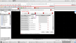
Set the form entries:Hughes said:Another method is as follows:
In the schematic window, select menu 'Edit/Label Display...', set the form entries:
Select Label: parameter
Apply To: cell
Then select a instance.
xuel said:Set the form entries:Hughes said:Another method is as follows:
In the schematic window, select menu 'Edit/Label Display...', set the form entries:
Select Label: parameter
Apply To: cell
Then select a instance.
why no form appear.
ccw27 said:Is there a limit on the number of transistor parameters you can display? Because for pmos I have id, vgs, vth, vds and vdsat and all of them are displayed, however for nmos vdsat is not displayed. Is there any way around it?
cadence cdsparam
I want to see the vth and gm, operating region (satutation, linear, cutoff) of the transistors. And I want that these values have more digits. How could I do that?
Thanks in advance.
")
This is good for the transistor/transistors you select. But how can you do it for every transistor in the circuit, then save the settings and reuse them for another, completely different circuit without going through the choose device/set parameter cycle again?
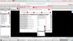
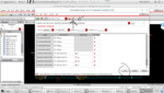
check out the images I've attached.When I do a DC analysis and click annotate DC Operating Points it displays "id, vgs and vds". I would like it to include "vdsat" as well, how can I do that?
Thanks
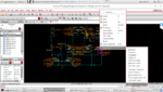
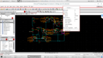
you can save the cdf parameters as default and it'll appear for every schematic. check out the attachment for reference.Thanks. But then how do you use this same annotation setup on a completely different schematic without going through the same steps of choosing the DC parameters again?
Save setup and then load it for new session or even load it during virtuoso start in cdsinit?Thanks. But then how do you use this same annotation setup on a completely different schematic without going through the same steps of choosing the DC parameters again?