Continue to Site

Welcome to EDAboard.com

Welcome to our site! EDAboard.com is an international Electronics Discussion Forum focused on EDA software, circuits, schematics, books, theory, papers, asic, pld, 8051, DSP, Network, RF, Analog Design, PCB, Service Manuals... and a whole lot more! To participate you need to register. Registration is free. Click here to register now.

[SOLVED] How to add a 12V fan switching circuit from a current design?

Status
Not open for further replies.

hafrse

Full Member level 3
Joined
Aug 6, 2007
Messages
169
Helped
1
Reputation
2
Reaction score
3
Trophy points
1,298
Activity points
2,413
Hello,

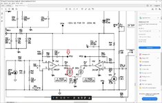
I need to add a small 40x40mm fan that switches on or off from a current design in a power supply:

According to the schematics (attached in this thread) , there is a red LED diode that switches on when the voltage at TPS2 is 4V and the LED switches off when TPS2 is 0.3V, I need to use that to control the fan to switch on or off with a switching circuit using transisitor(s) without overloading the circuit at TPS2.

The fan ratings are 12V at 0.1A. The only available power supply to the new circuit and the fan is 22V but I could use a series resistor to limit the voltage to 12V

Many thanks in advance!
George
 

Attachments

  • fan.jpg
    fan.jpg
    382.3 KB · Views: 127

Hi,

don´t use a resistor or a resistive voltage divider to reduce the voltage from 22V to 12V. Use a 10V zener instead.
Mind it will dissipate 1W. Use a zener with much headroom in power dissipation.
The A better way is to use a 24V fan, it will work with 22V.

To switch the fan you may use:
* a darlington NPN and a base resistor
* a logic level MOSFET
* a logic controlled dedicated low side switch
* a logic controlled dedicated high side switch.
* other solutions.

In any case I recommend an overvoltage protection diode to protect the switch.

There is no "one and only" solution, there is no "general best" solution. You have to decide which one suits you best.

Klaus
 

    hafrse

    Points: 2
    Helpful Answer Positive Rating
Thanks,

Great, I happen to have a N-chnnel NDS9410A logic level MOSFET, should I add a resistor of 1K from the Gate to gnd andd7or any series resistor from TPS5 to the Gate?

Thanks
 

No pull-down resistor required because TPS2 is pulled low by the driving OP in inactive state. You should be however aware, that TPS2 can swing to about +20V during I/U controller overshoot which would kill the MOSFET. A series resistor/Z-diode combination driving the gate should be added for protection purposes. The bipolar transistor solution doesn't have the problem.
 

    hafrse

    Points: 2
    Helpful Answer Positive Rating
Hi,

No need for an additional resistor ... if the given values are valid.

Take care about ESD when soldering.

Klaus
 

    hafrse

    Points: 2
    Helpful Answer Positive Rating
Wired now, works fin! thanks all for you help!


Thanks

--- Updated ---

Hi,

No need for an additional resistor ... if the given values are valid.

Take care about ESD when soldering.

Klaus
@KlausST: Can you please explain why I can't use a resistor in series with the 12V fan? and if I should use a zener diode, where should I place it ?

Thanks
--- Updated ---

After testing , it seems that I am not able to use TPS2 to drive the MOSFET, sometimes , the power supply switches between U and I mode back and forth many times (Power supply mode/ charging mode). Any clue? this also happens if I diconnect the fan. with the gate attached to the MOSFET and the source to ground.

Any clues ? thanks

Thanks
 
Last edited:

Can you please explain why I can't use a resistor in series with the 12V fan? and if I should use a zener diode, where should I place it
Place the zener instead the resistor.
The voltage across a resistor is proportional to the current.
Low current = low voltage drop
High current = high voltage drop.
The current of a fan is not constant, thus the voltage drop is not constant.

The voltage drop across a zener is almost constant.
*******

After testing , it seems that I am not able to use TPS2 to drive the MOSFET, sometimes , the power supply switches between U and I mode back and forth many times (Power supply mode/ charging mode). Any clue? this also happens if I diconnect the fan. with the gate attached to the MOSFET and the source to ground.
I guess it's not the problem of the TPS2. I rather guess it's the problem of the 22V or the GND wiring.

Klaus
 

    hafrse

    Points: 2
    Helpful Answer Positive Rating
Thanks! correct, the issue was not from the TPS2 signal , it was the external instrument that controls the charge , I have now orderd a Znerer diode, however it looks to work now :)
 

Status
Not open for further replies.

Part and Inventory Search

Welcome to EDABoard.com

Sponsor

Back
Top