Continue to Site

Welcome to EDAboard.com

Welcome to our site! EDAboard.com is an international Electronics Discussion Forum focused on EDA software, circuits, schematics, books, theory, papers, asic, pld, 8051, DSP, Network, RF, Analog Design, PCB, Service Manuals... and a whole lot more! To participate you need to register. Registration is free. Click here to register now.

how to abaut GLCD pins

Status
Not open for further replies.

hesho90

Member level 4
Joined
Sep 3, 2012
Messages
78
Helped
0
Reputation
0
Reaction score
0
Trophy points
1,286
Location
egypt
Activity points
1,778
how to abaut GLCD pins

and witch one to sbit to with the PIC

this my pins

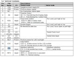
VCC VDD NC A0 NC E D0...D7 BLA CS1 PS RES
 

If I understand your problem, you need to find out how to connect GLCD and microcontroller. On this site you have a described one professional development board based on PIC microcontrollers and there are connections for GLCD.

If you download user manual from this site, you will see how is GLCD connect to PIC.

web site about development board

**broken link removed**

**broken link removed**

i want to know what one i coonect with my pic cz i didnt see this pins befor
 

Glcd 128x64 jhd1286

GLCD.PNG
 

Using the name, I find a datasheet for your GLCD - **broken link removed**

Where you seen NC pin on your schematic? Usually that means NC - Not Connect.
 

Using the name, I find a datasheet for your GLCD - **broken link removed**

Where you seen NC pin on your schematic? Usually that means NC - Not Connect.

tyvm man you where very nice

my GLCD IS LM13232

AND I do it like that but the code get eror till me where is
rs and cs2 and my lcd dont have them
 

Attachments

  • MK-002937-1-1(LM13232AFW-1 Outline).pdf
    46.7 KB · Views: 87
  • LM13232AFW-Manual-Rev0.2.pdf
    207.3 KB · Views: 78
  • Note for use LCD in Serial Mode.pdf
    8.2 KB · Views: 128

OK, now we have a documentation about GLCD. Could we define problem again and then try to solve it?

Which microcontroller you plan to use?
Did you make any schematic of your device?
Do you have any example for it?
 

Thank you replying

i use PIC16F877A

I DID make a example and it have errors on ISIS

and the schematic

but the code Always RS RST CS2 AND THINGS my lcd dont have it in it pins

AND my code is


Code C - [expand]
1
2
3
4
5
6
7
8
9
10
11
12
13
14
15
16
17
18
19
20
21
22
23
24
25
26
27
28
29
sbit GLCD_A0 at RB0_bit;
sbit GLCD_EN at RB1_bit;
sbit GLCD_CS1 at RB2_bit;
sbit GLCD_PS at RB3_bit;
sbit GLCD_D4 at RB4_bit;
sbit GLCD_D5 at RB5_bit;
sbit GLCD_D6 at RB6_bit;
sbit GLCD_D7 at RB7_bit;
 
 
sbit GLCD_A0_Direction at TRISB0_bit;
sbit GLCD_EN_Direction at TRISB1_bit;
sbit GLCD_CS1_Direction at TRISB2_bit;
sbit GLCD_PS_Direction at TRISB3_bit;
sbit GLCD_D4_Direction at TRISB4_bit;
sbit GLCD_D5_Direction at TRISB5_bit;
sbit GLCD_D6_Direction at TRISB6_bit;
sbit GLCD_D7_Direction at TRISB7_bit;
 
void main()
{
  GLcd_Init();


  Lcd_Out(1,1,"hello");
 
  Delay_ms(2000);
}


and after i press build on mikroc it get
0 1 mikroCPIC1618.exe -MSF -DBG -pP16F877A -DL -O11111114 -fo8 -N"F:\leds\ãÌáÏ ÌÏíÏ\code\code.mcppi" -SP"D:\Program Files\Mikroelektronika\mikroC PRO for PIC\defs\" -SP"D:\Program Files\Mikroelektronika\mikroC PRO for PIC\Uses\P16\" -SP"F:\leds\ãÌáÏ ÌÏíÏ\code\" "code.c" "__Lib_Math.mcl" "__Lib_MathDouble.mcl" "__Lib_System.mcl" "__Lib_Delays.mcl" "__Lib_CType.mcl" "__Lib_CString.mcl" "__Lib_CStdlib.mcl" "__Lib_CMath.mcl" "__Lib_Conversions.mcl" "__Lib_Sprinti.mcl" "__Lib_Sprintl.mcl" "__Lib_Time.mcl" "__Lib_Trigonometry.mcl" "__Lib_Button.mcl" "__Lib_Keypad4x4.mcl" "__Lib_Manchester.mcl" "__Lib_OneWire.mcl" "__Lib_PS2.mcl" "__Lib_Sound.mcl" "__Lib_SoftI2C.mcl" "__Lib_SoftSPI.mcl" "__Lib_SoftUART.mcl" "__Lib_ADC_A_C.mcl" "__Lib_EEPROM.mcl" "__Lib_FLASH_RW.mcl" "__Lib_I2C_c34.mcl" "__Lib_PWM_c21.mcl" "__Lib_SPI_c345.mcl" "__Lib_UART_c67.mcl" "__Lib_PortExpander.mcl" "__Lib_CANSPI.mcl" "__Lib_CF.mcl" "__Lib_GlcdFonts.mcl" "__Lib_Glcd.mcl" "__Lib_LcdConsts.mcl" "__Lib_Lcd.mcl" "__Lib_RS485.mcl" "__Lib_T6963C.mcl" "__Lib_SPIGlcd.mcl" "__Lib_SPILcd.mcl" "__Lib_SPILcd8.mcl" "__Lib_SPIT6963C.mcl" "__Lib_EthEnc28j60.mcl" "__Lib_EthEnc24j600.mcl" "__Lib_TouchPanel.mcl"
0 1139 Available RAM: 352 [bytes], Available ROM: 8192 [bytes]
0 126 All files Preprocessed in 1 ms
0 122 Compilation Started code.c
29 123 Compiled Successfully code.c
0 127 All files Compiled in 63 ms
0 360 Unresolved extern 'GLCD_RST_Direction' __Lib_Glcd.c
0 360 Unresolved extern 'GLCD_RS_Direction' __Lib_Glcd.c
0 360 Unresolved extern 'GLCD_RW_Direction' __Lib_Glcd.c
0 360 Unresolved extern 'GLCD_CS2_Direction' __Lib_Glcd.c
0 360 Unresolved extern 'GLCD_RST' __Lib_Glcd.c
0 360 Unresolved extern 'GLCD_DataPort' __Lib_Glcd.c
0 360 Unresolved extern 'GLCD_RS' __Lib_Glcd.c
0 360 Unresolved extern 'GLCD_RW' __Lib_Glcd.c
0 360 Unresolved extern 'GLCD_CS2' __Lib_Glcd.c
0 360 Unresolved extern 'LCD_D7' __Lib_Lcd.c
0 360 Unresolved extern 'LCD_D6' __Lib_Lcd.c
0 360 Unresolved extern 'LCD_D5' __Lib_Lcd.c
0 360 Unresolved extern 'LCD_D4' __Lib_Lcd.c
0 360 Unresolved extern 'LCD_RS' __Lib_Lcd.c
0 360 Unresolved extern 'LCD_EN' __Lib_Lcd.c
0 102 Finished (with errors): 06 ÓÈÊãÈÑ 2012, 22:44:35 code.mcppi
- - - Updated - - -

i found that C file that come with it but it not in eng
 

Attachments

  • eeee.bmp
    297.8 KB · Views: 71
  • photo.bmp
    934.4 KB · Views: 64
  • TOPWAY-ST7565(67)-AppPro-v0.1.rar
    5 KB · Views: 64
Last edited by a moderator:

Did you write this part of code or you took it from manual or some example?

Code:
sbit GLCD_A0 at RB0_bit;
sbit GLCD_EN at RB1_bit;
sbit GLCD_CS1 at RB2_bit;
sbit GLCD_PS at RB3_bit;
sbit GLCD_D4 at RB4_bit;
sbit GLCD_D5 at RB5_bit;
sbit GLCD_D6 at RB6_bit;
sbit GLCD_D7 at RB7_bit;
 
 
sbit GLCD_A0_Direction at TRISB0_bit;
sbit GLCD_EN_Direction at TRISB1_bit;
sbit GLCD_CS1_Direction at TRISB2_bit;
sbit GLCD_PS_Direction at TRISB3_bit;
sbit GLCD_D4_Direction at TRISB4_bit;
sbit GLCD_D5_Direction at TRISB5_bit;
sbit GLCD_D6_Direction at TRISB6_bit;
sbit GLCD_D7_Direction at TRISB7_bit;

I think, you must add some lines of code. I use mikroC also, but for AVR. But, I believe, that is very similar.

Maybe, you can find some example on mikroe.com web site for GLCD

- - - Updated - - -

This is how my code looks like (but, do not forget, I used EasyAVR5a development board and GLCD 128x64):

Code:
// Glcd module connections
char GLCD_DataPort at PORTC; // port for Data Bus Line
char GLCD_DataPort_Direction at DDRC; // port direction

sbit GLCD_CS1 at PORTD.B2; // Select segment 1 - 64
sbit GLCD_CS2 at PORTD.B3; // Select segment 65 - 128
sbit GLCD_RS  at PORTD.B4; // High: Data; Low: Instruction
sbit GLCD_RW  at PORTD.B5; // High: Read, Low: Write
sbit GLCD_EN  at PORTD.B6; // High: Enable signal
sbit GLCD_RST at PORTD.B7; // Reset the LCM
sbit GLCD_CS1_Direction at DDRD.B2;
sbit GLCD_CS2_Direction at DDRD.B3;
sbit GLCD_RS_Direction  at DDRD.B4;
sbit GLCD_RW_Direction  at DDRD.B5;
sbit GLCD_EN_Direction  at DDRD.B6;
sbit GLCD_RST_Direction at DDRD.B7;
// End Glcd module connections

 
  • Like
Reactions: hesho90

    hesho90

    Points: 2
    Helpful Answer Positive Rating
Thank you replying


i did this code my self

the one you give me never wark becase the RST AND CS2 and more are not in my GLCD pdfs and mikroc dont want to make the code without them so how can i make the code with the ports and pins in hand

VCC VDD NC A0 NC E D0...D7 BLA CS1 PS RES

how make a GLCD code without the ports and pins that mikroc want me to give him
 

Now we have a clear problem. You know, mikroC intended GLCD library for 128x64 GLCD. How they said in the manual:


Graphic Lcd Library
The mikroC PRO for AVR provides a library for operating Graphic Lcd 128x64 (with commonly used Samsung KS108/KS107 controller).

For creating a custom set of Glcd images use Glcd Bitmap Editor Tool.


I take this text from manual for mikroC PRO for AVR. Please, look in manual for mikroC which you use, but I think it will write the same.

I look on the site of manufacture of your GLCD, but I did not find which controller is used in it.

I suggest you to send email for asking support and help from Mikroelektronika, or first at all, you may read manual for mikroC for GLCD library. I did not use Glcd Bitmap Editor, but I believe it is not something to complicate.

Mikroelektronika also have a forum, like this, and maybe you can find some answers on that place.
 
  • Like
Reactions: hesho90

    hesho90

    Points: 2
    Helpful Answer Positive Rating
Thank you replying


but what i get from this GLCD 132x32 hard to use i try to make in seril mode if i can

sch1.JPG

sch.JPG

i will make connet on ISIS like this

all of d0..d7 to portd of the pic and p/s and e and i dont know what ales to portb
but how is the code going to be like

and i wana Thank you for the great help you give
 

Ok, but I am sorry because I can not help you more.

My experience with GLCD is that part of electronic devices is not still standardise enough between manufactures. And, documentation is bad, datasheets are not good and helpful enough for begginers, like microcontroller datasheets are. When I try to find some examples of libraries for my GLCD on the internet, I had not any success. And, I give up, and start to use mikroe library, I just did not know how to write the library.

Best regard!
 

Status
Not open for further replies.

Similar threads

Part and Inventory Search

Welcome to EDABoard.com

Sponsor

Back
Top