Continue to Site
Follow along with the video below to see how to install our site as a web app on your home screen.
Note: This feature may not be available in some browsers.
hello
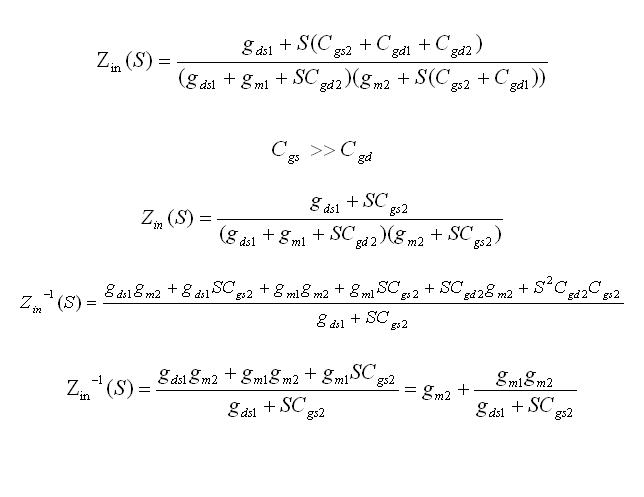
I read this equation in a thesis but I cant understand with what assumption the result drive, can anyone help me?

hello
I read this equation in a thesis but I cant understand with what assumption the result drive, can anyone help me?
")
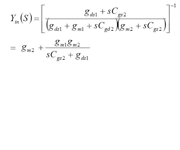
(2) is (1) written with matrices, just hard to make matrices with text, plus multiple spaces are stripped from your formatting so the result is hard to understand.Hi dgnani
I try to do your calculation at #8 answer, but I cant understand how you write (2) from (1) :sad:
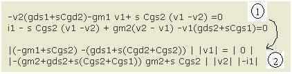
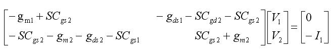
yes I understand that you write in matrices form like:
now after calculation complete formula of Y1(S) from this matrices what assumption I shoud consider to drive your Y1(S)? (for example Cgs>>Cgd)
I mean Y(S)oh sorry I wrote wrong
ok then with this 2 assumption I can drive your final Y(S) equation, now Is this Y(S) valid for all range of frequency or it is valid just for low frequency?