Continue to Site

Welcome to EDAboard.com

Welcome to our site! EDAboard.com is an international Electronics Discussion Forum focused on EDA software, circuits, schematics, books, theory, papers, asic, pld, 8051, DSP, Network, RF, Analog Design, PCB, Service Manuals... and a whole lot more! To participate you need to register. Registration is free. Click here to register now.

How remove DC offset from AC?

Status
Not open for further replies.

ygor1

Newbie level 5
Joined
Feb 23, 2013
Messages
8
Helped
0
Reputation
0
Reaction score
0
Trophy points
1,281
Activity points
1,333
Hello,
I have amplifier say AD8021, amplifier work to 50ohm load, frequency 100Hz-1MHz, Gain=10, output amplitude +- 2,5V. AD8021 have input offset 1mV
I need remove DC offset, question is how?
I think add on output capacitor or more precisely several capacitors parallel.
Question is what to use capacitors that on them was minimal attenuation, output was linear over frequency 100Hz-1MHz.
My idea is 1000uF (LXZ Nippon) + 10uF ceramic + 100nF ceramic
It is a great folly, or, it's better to solve
 

That is one solution and it should work OK.

The other is to do the opposite - connect the signal to a filter to remove the AC then subtract the result from the input. This is fairly easy if you use an amplifier with differential inputs because you can apply it to the other input to cancel the DC. If you use this method, and the DC is fairly constant, you can use a simple RC filter with a cut-off at say 10Hz.

Brian.
 

I know that it is me is more about what makes a 1000uF capacitor, which will pass high frequency, 1MHz, but also 100MHz.
What will be the effect on C passing frequency (sine wave), it will act as a capacitor antenna
 

In case this helps...

Although you state a 50 ohm load, it is a good idea to test different capacitor values, to obtain your desired rolloff curve.

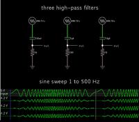
Here is a simulation showing how three different RC values can yield the same time constant, thus yielding the same rolloff curve.


Values increase or decrease in multiples of 10.

Comparing the values it becomes obvious how the capacitor value together with the overall resistance, combine to determine how the filter responds.
 

Status
Not open for further replies.

Part and Inventory Search

Welcome to EDABoard.com

Sponsor

Back
Top